Functions
6-2457SA6 Manual
C53000-G1176-C133-1
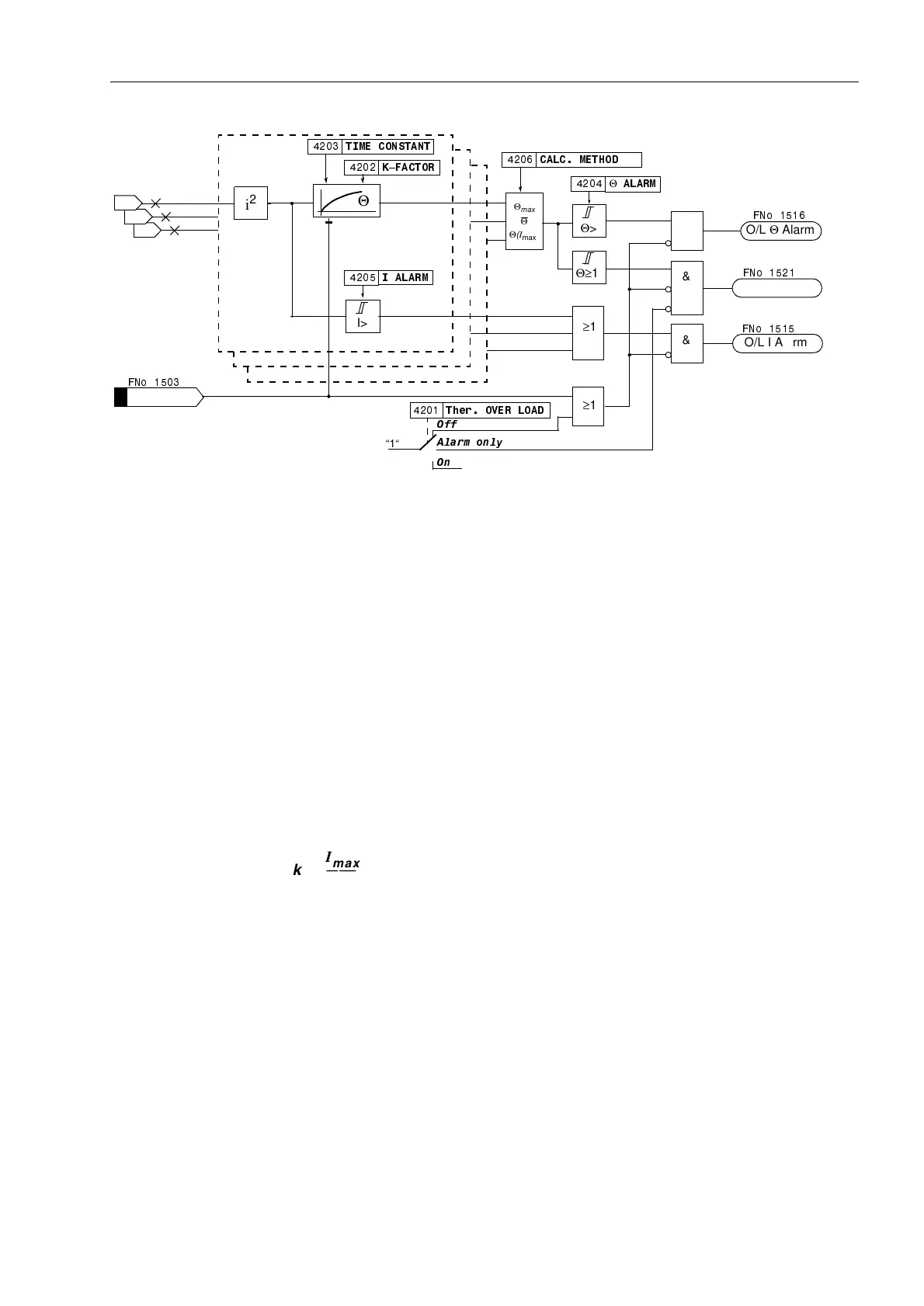
Figure 6-129 Logic diagram of the thermal overload protection
6.17.2 Applying the Function Parameter Settings
General
Information
A precondition for the use of the thermal overload protection is that 2YHUORDG =
(QDEOHG was configured under address (Section 5.1). It can be switched 2Q or
2II under address 7KHU29(5/2$'. Furthermore $ODUP 2QO\ can be set.
With that latter setting the protection function is active but only outputs an alarm when
the tripping temperature is reached, i.e. the output function “7K2/75,3” is not
active.
k–factor The rated current of the device is taken as the base current for detecting an overload.
The setting factor k is set under address .)$&725. It is determined by the
relation between the permissible thermal continuous current and this rated current:
The permissible continuous current is at the same time the current at which the e-
function of the overtemperature has its asymptote. It is not necessary to determine the
tripping temperature since it results automatically from the final rise temperature at
k · I
N
. Manufacturers of electrical machines usually state the permissible continuous
current. If no data are available, k is set to 1.1 times the rated current of the protected
object. For cables, the permissible continuous current depends on the cross section,
the insulation material, the design and the way they are laid, and can be derived from
the relevant tables.
Please note that the overload capability of electrical equipment relates to its primary
current. This has to be considered if the primary current differs from the rated current
of the current transformers.
L3
L2
L1
I
L3
I
L2
I
L1
O/L blocked
Th.O/L TRIP
&
7,0(&2167$17
Θ
.²)$&725
I>
,$/$50
&$/&0(7+2'
Θ>
Θ
$/$50
Θ
max
Θ
Θ
(
I
max
)
Θ≥1
&
&
O/L I Alarm
O/L Θ Alarm
≥1
7KHU29(5/2$'
$ODUPRQO\
2II
2Q
“1“
)1R
)1R
)1R
)1R
i
2
≥1
k
I
max
I
N
------------
=

 Loading...


