Installation and Commissioning
8-237SA6 Manual
C53000-G1176-C133-1
.
With device versions 7SA6*2–A... and 7SA6*2–B... (housing size
1
/
1
) the contact of
input/output boards C–I/O–1 (Figure 8-13, slot 19 left and right, as well as slot 33 left)
the relays for the binary outputs BO9, BO17 and BO25 (depending on the version) can
be changed from normally closed to normally open (refer to General Diagrams in
the Appendix A under Section A.2).
Checking control voltages of binary inputs:
BI6 to BI13 (for housing size
1
/
2
) according to Table 8-9,
BI6 to BI29 (for housing size
1
/
1
, depending on version) according to Table 8-10.
1
) Factory settings for devices with power supply voltages of 24 VDC to 125 VDC
2
) Factory settings for devices with power supply voltages of 110 VDC to 250 VDC and 115 VAC
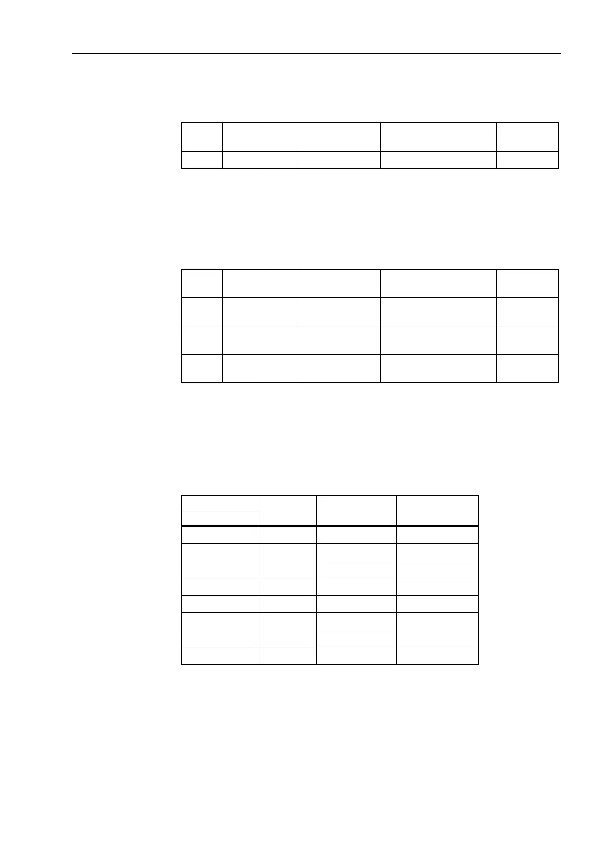
Table 8-7 Jumper setting for the contact type of relay for BO9
Module for Jumper
Quiescent state
open (NO contact)
Quiescent state
closed (NC contact)
Presetting
Slot 19 BO9 X40 1–2 2–3 1–2
Table 8-8 Jumper setting for the contact type of relay for BO9, BO17 and BO25
Module for Jumper
Quiescent state
open (NO contact)
Quiescent state
closed (NC contact)
Presetting
Slot 33
left
BO9 X40 1–2 2–3 1–2
Slot 19
right
BO17 X40 1–2 2–3 1–2
Slot 19
left
BO25 X40 1–2 2–3 1–2
Table 8-9 Jumper setting of control voltages of binary inputs BI6 to BI13 on the binary in-
put/output boards C– I/O–1 for housing size
1
/
2
Binary inputs
Jumper
Threshold 17 V
1
) Threshold 73 V
2
)
Slot 19
BI6 X21/X22 L M
BI7 X23/X24 L M
BI8 X25/X26 L M
BI9 X27/X28 L M
BI10 X29/X30 L M
BI11 X31/X32 L M
BI12 X33/X34 L M
BI13 X35/X36 L M

 Loading...


