Installation and Commissioning
8-22 7SA6 Manual
C53000-G1176-C133-1
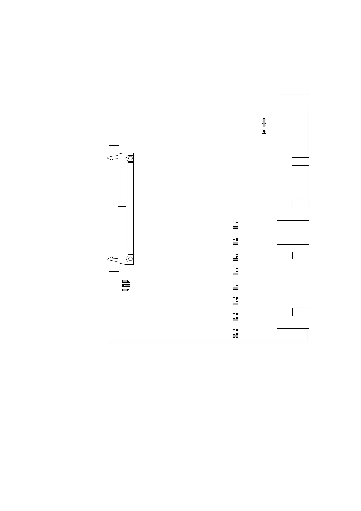
Input/Output Board
C-I/O-1
The layout of the printed circuit board for the input/output board C-I/O–1 is illustrated
in Figure 8-13.
Figure 8-13 The input/output board C–I/O–1 with the jumpers necessary for the control of
settings
For the input/output boards C–I/O–1 (Figure 8-13, Slot 19) of device version
7SA6*1-A... (housing size
1
/
2
) it is possible to change the contact of the output relay
for the binary output BO9 from normally open to normally closed (refer to General
Diagrams in the Appendix A, Section A.2).
HLM
X22
X21
HLM
X24
X23
HLM
X26
X25
HLM
X28
X27
HLM
X30
X29
HLM
X32
X31
HLM
X34
X33
HLM
X36
X35
X40
3
1
2
X71
(AD0)
HL
X72
(AD1)
X73
(AD2)

 Loading...


