Installation and Commissioning
8-217SA6 Manual
C53000-G1176-C133-1
The jumper presetting is dependent on the order code of the device.
For RS232 (12th digit of order code = 0, 1): setting 1–2
For RS485 (12th digit of order code = 2: setting 2–3
If there are no external matching resistors in the system, the last devices on a
RS485-bus must be configured via jumpers X103 and X104.
Note: Both jumpers must always be plugged in the same way!
Currently no function is assigned to the jumper X90. The presetting is 1-2.
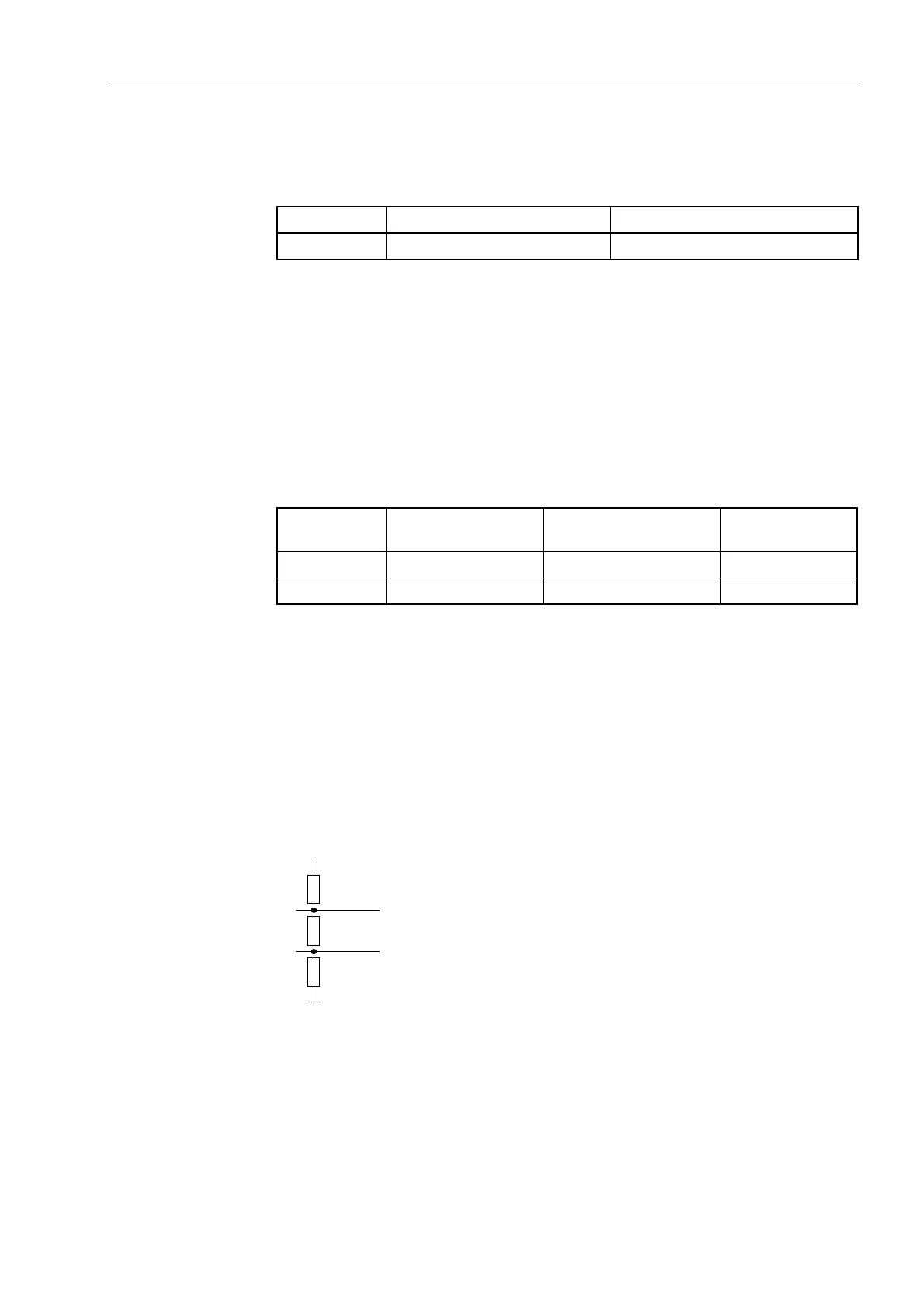
The terminating resistors can also be connected externally (e.g. to the connection
module). In this case, the terminating resistors located on the RS485 or the Profibus
interface module or the resistors located directly on the processor circuit board C–
CPU–2 must be disconnected.
Figure 8-12 Termination of the RS 485 interface (external)
Table 8-5 Jumper setting of CTS (Clear-To-Send) on the processor printed circuit
board C-CPU-2
Jumper /CTS of interface RS232 /CTS controlled by /RTS
X111 1–2 2–3
Table 8-6 Jumper setting of matching resistors of the interface RS485 on the processor
printed circuit board C–CPU–2
Jumper Matching resistor
closed
Matching resistor
open
Presetting
X103 2–3 1–2 1–2
X104 2–3 1–2 1–2
390 Ω
220 Ω
390 Ω
+5 V
A/A´
B/B´

 Loading...


