Functions
6-97SA6 Manual
C53000-G1176-C133-1
this difference must also be considered:
Address: 8OLQH8V\QF= 100 V/ 110 V =
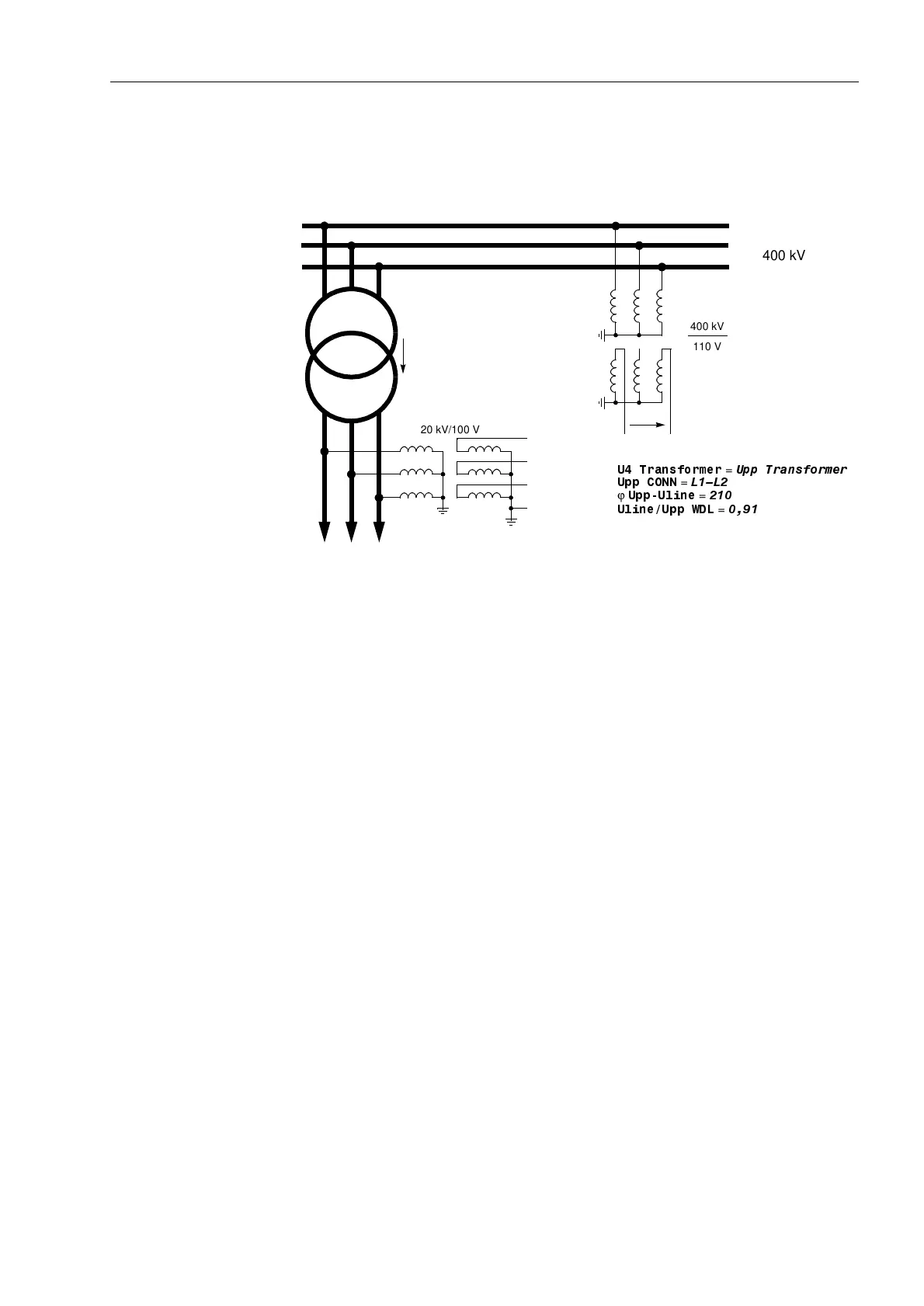
Figure 6-9 Busbar voltage, measured across a power transformer
• Connection of the U
4
input to any other voltage signal U
X
, which may be processed
by the overvoltage protection function, refer to Appendix A, Figure A-27:
Address is then set: 8WUDQVIRUPHU = 8[WUDQVIRUPHU.
It is assumed, that the Ux transformer ratio is equal to the phase voltage
transformer ratio.
• If the U
4
input is not required, the following setting is applied:
Address 8WUDQVIRUPHU = 1RWFRQQHFWHG.
Also in this case the factor 8SK8GHOWD (Address , refer to the above) is
of importance, as it is utilised for the scaling of the measurement and disturbance
recording signals.
Current
Transformer
Connection
The device contains four current measurement inputs, three of which are connected
to the set of current transformers. The fourth current measuring input I
4
may be utilised
in various ways:
• Connection of the I
4
input to the earth current in the starpoint of the set of current
transformers on the protected feeder (normal connection, refer to Appendix A,
Figure A-20):
Address is then set to: ,WUDQVIRUPHU = ,QSURWOLQH and
Address to ,,SK&7 = 1.
• Connection of the I
4
input to a separate earth current transformer on the protected
feeder (e.g. a summation CT or cable-type current transformer, refer to Appendix
A, e.g. Figure A-21).
Address is then set to: ,WUDQVIRUPHU = ,QSURWOLQH and
Address is set to,,SK&7:
L1
L2
L3
U
L1
U
L2
U
L3
(any voltage)
U
E
U
SS
feeder
Busbar
Yd5
220 kV
400 kV/220 kV
87UDQVIRUPHU
=
8SS7UDQVIRUPHU
8OLQH8SS:'/
=
8SS&211
=
/²/
ϕ
8SS8OLQH
=
°
220 kV/100 V
400 kV
110 V
400 kV

 Loading...


