Functions
6-1277SA6 Manual
C53000-G1176-C133-1
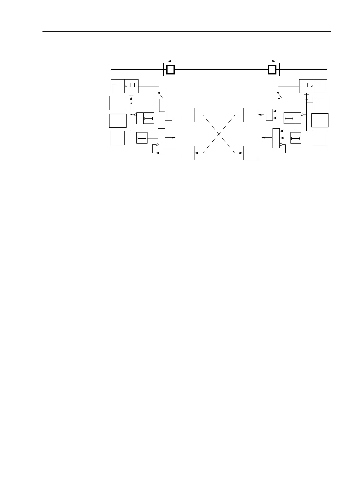
Figure 6-75 Operation scheme of the directional blocking method
Sequence Figure 6-76 shows the logic diagram of the blocking scheme for one line end.
The stage to be blocked must be set to )RUZDUG (,',5(&7,21); also refer
to Sub-section 6.5.2 under margin heading „Teleprotection with Earth Fault
Protection“.
The occurrence of erroneous signals resulting from transients during clearance of
external faults or from direction reversal resulting during the clearance of faults on
parallel lines, is neutralized by the “Transient Blocking”. It prolongs the blocking signal
by the transient blocking time 7U%ON%ORFN7LPH (address ), if it has been
present for the minimum duration equal to the waiting time 7U%ON:DLW7LPH
(address ).
It lies in the nature of the blocking scheme that earth faults with single sided infeed can
be rapidly cleared without any special measures, as the non feeding end does not
generate a blocking signal.
On three terminal lines, the transmit signal is sent to both opposite line ends. The
receive signal is then combined with a logical
OR
gate as no blocking signal must be
received from any line end during an internal fault. With the setting parameter /LQH
&RQILJ (address ) the device is informed as to whether it has one or two
opposite line ends.
AB
EF/
FD
trip
rec.
&
d
dt
40 ms
T
S
&
≥1
transm.
(u,i)
3I0 Min
Telep.
(A)
T
V
EF/
FD
trip
rec.
&
d
dt
40 ms
T
S
&
≥1
transm.
(u,i)
(B)
T
V
E/F.
forwd.
E/F.
forwd.
3I0 Min
Telep.
EF/FD = Pickup by any E/F stage

 Loading...


