Functions
6-176 7SA6 Manual
C53000-G1176-C133-1
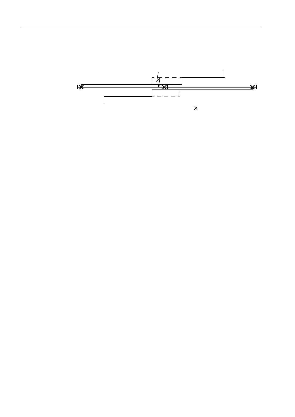
Line A–B is tripped at both ends. There is therefore no voltage here, this identifies the
line at both ends as the faulted one. The normal dead time comes into service here.
Figure 6-95 Example of a reduced dead time (RDT)
Adaptive
Dead Time (ADT)
In all the previous alternatives it was assumed that defined and equal dead times were
set at both line ends, if necessary for different fault types and/or reclose cycles.
It is also possible to set the dead times (if necessary different for various fault types
and/or reclose cycles) at one line end only and to configure the adaptive dead time
(ADT) at the other end (or ends). This can be done on condition that the voltage
transformers are located on the line side of the circuit breaker or that means for the
transfer of a close command exist.
Figure 6-96 shows an example. It is assumed that the device I is operating with
defined dead times whereas the adaptive dead time is configured at position II. It is
important that the line is at least fed from busbar A, i.e. the side with the defined dead
times.
With the adaptive dead time the automatic reclosure function at line end II decides
independently if and when reclosure is sensible and is therefore allowed and when it
is not. The criterion is the voltage on the line at end II, which is fed from end I following
reclosure there. Reclosure therefore takes place at end II as soon as it is apparent that
voltage has been re-applied to the line from end I.
In the illustrated case, the lines are tripped at positions I, II and III. At I reclosure takes
place after the dead time parameterized there. At III a reduced dead time can take
place (see above) if there is also an infeed on busbar B.
If the fault has been cleared (successful reclosure), line A–B is re-energised from
busbar A through position I. Device II detects this voltage and also reclosed after a
short delay (to ensure a sufficient voltage measuring time). The system fault has
ended.
If the fault has not been cleared after reclosure at I, a switch on to fault occurs at I, no
healthy voltage appear at II. The device there detects this and does not reclose.
In the case of multiple reclosure the sequence may be repeated several times
following an unsuccessful reclosure until one of the reclosures attempts is successful
or a final trip takes place.
Z1B
A, B, C busbars
I, II, III relay locations
tripped circuit-breakers
Z1
Z1B
Z2
Z1
ABC
III III

 Loading...


