Functions
6-230 7SA6 Manual
C53000-G1176-C133-1
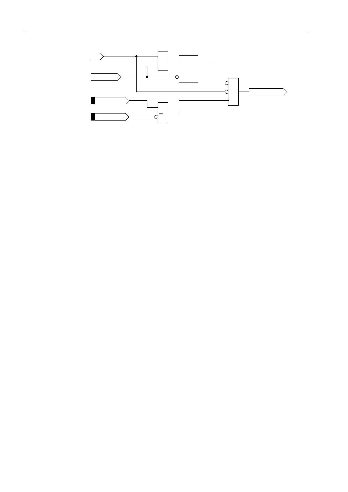
Figure 6-114 Interlock of the auxiliary contact criterion — example for phase L1
On the other hand, current flow is not a reliable criterion for proper operation of the
circuit breaker for faults which do not cause detectable current flow (e.g. Buchholz
protection). Information regarding the position of the circuit breaker auxiliary contacts
is required in these cases to check the correct response of the circuit breaker. For this
purpose, the binary input “!%)6WDUWZR,” is provided (Figure 6-116 left). This
input initiates the breaker failure protection even if no current flow is detected.
Common Phase
Initiation
Common phase initiation is used, for example, for lines without automatic reclosure,
for lines with only three-pole automatic reclosure, for transformer feeders, or if the bus-
bar protection trips. This is the only available initiation mode if the actual 7SA6 model
is able to trip three-pole only.
If the breaker failure protection is intended to be initiated by further external protection
devices, it is recommended, for security reasons, to connect two starting criteria to the
7SA6 device: the trip command to the input “!%)6WDUWSROH” and an additional
release signal (e.g. fault detection, pickup) to the input ´!%)UHOHDVH”. For Buchholz
protection it is recommended that the trip command is connected to the 7SA6 by two
separate wire pairs in order to achieve dual-channel initiation of the breaker failure
protection.
Nevertheless, it is possible to initiate the breaker failure protection in single-channel
mode should a separate release criterion not be available. The binary input ´!%)
UHOHDVH” must then not be assigned to any physical input of the device during
configuration.
The scheme functionality is shown in Figure 6-116. When the trip signal appears from
any internal or external feeder protection and at least one current flow criterion
(according to Figure 6-113) is present, the breaker failure protection is initiated and
the corresponding delay time(s) is (are) started.
If the current criterion is not fulfilled for any of the phases the position of the circuit
breaker auxiliary contact(s) is interrogated provided that this is available. If the circuit
breaker poles have individual auxiliary contacts, the series connection of the three
normally closed (NC) auxiliary contacts is used. The circuit breaker has operated
correctly after a three-pole trip command only when none of the phases carries current
or when all three NC auxiliary contacts have closed.
Figure 6-115 illustrates how the internal signal
“CB pole L1 closed” is created (see
Figure 6-116 left) if at least one circuit breaker pole is closed.
1
) if phase dedicated auxiliary contacts available
2
) if series connection of NC contacts available
&
>
1
&
L1>
>CB Aux. L1
Start only L1
>CB 3p Open
CB pole L1 closed
S
R
Q
1
)
2
)
FNo 351
FNo 380
(refer to Fig. 6-119)

 Loading...


