Functions
6-240 7SA6 Manual
C53000-G1176-C133-1
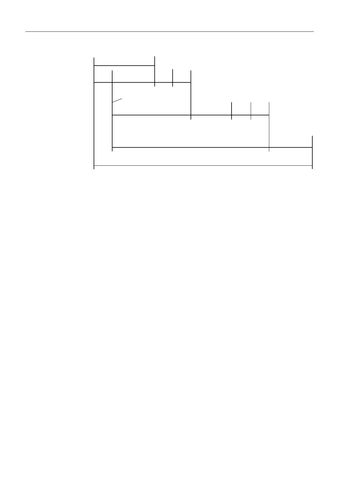
Figure 6-127 Time sequence example for normal clearance of a fault, and with circuit breaker
failure, using two-stage breaker failure protection
Single-stage
Breaker Failure
Protection
With single-stage operation, the adjacent circuit breakers (i.e. the breakers of the bus-
bar zone and — if transmission of the signal is possible — the breaker at the remote
end) are tripped after a delay time 7 (address ) following initiation, should the
fault not have been cleared within this time.
The timers 7SROH (address ) and 7SROH (address ) are then set to
∞ since they are not needed.
But you may use the T1-timers for single-stage protection if you wish to utilize the
facility of setting different delay times after single-pole trip and three-pole trip of the
feeder protection. In this case, set the desired times under addresses 7
SROH and 7SROH but set address S5(75,37 to 1R to avoid
a single-pole trip to the bus-bar. And set 7 (address ) to ∞ or equal to 7
SROH. Be sure that the correct trip commands are assigned to the desired trip
relay(s).
The delay times are determined from the maximum operating time of the feeder circuit
breaker, the reset time of the current detectors of the breaker failure protection, plus
a safety margin which allows for any tolerance of the delay timers. The time sequence
is illustrated in Figure 6-128. For sinusoidal currents one can assume that the reset
time of the current detectors is less than 12 ms but if current transformer saturation is
expected then 25 ms should be assumed.
Fault inception
Fault clearance time normal
Prot.
trip
CB operating time
(local)
Reset
I–BF
Safety
margin
CB operating time
(adjacent CBs)
Initiation breaker
failure protection
Time delay T1 of breaker
failure protection
Trip command
repetition
Reset
I> BF
Safety
margin
Time delay T2 of breaker
failure protection
Total fault clearance time with breaker failure

 Loading...


