Functions
6-2857SA6 Manual
C53000-G1176-C133-1
If the device is provided with the synchronism and voltage check, the characteristic
values (voltages, frequencies, differences) can be read out.
If the device is provided with the earth fault detection function for non-earthed
systems, the components of the earth current (active and reactive component) are
indicated, as well.
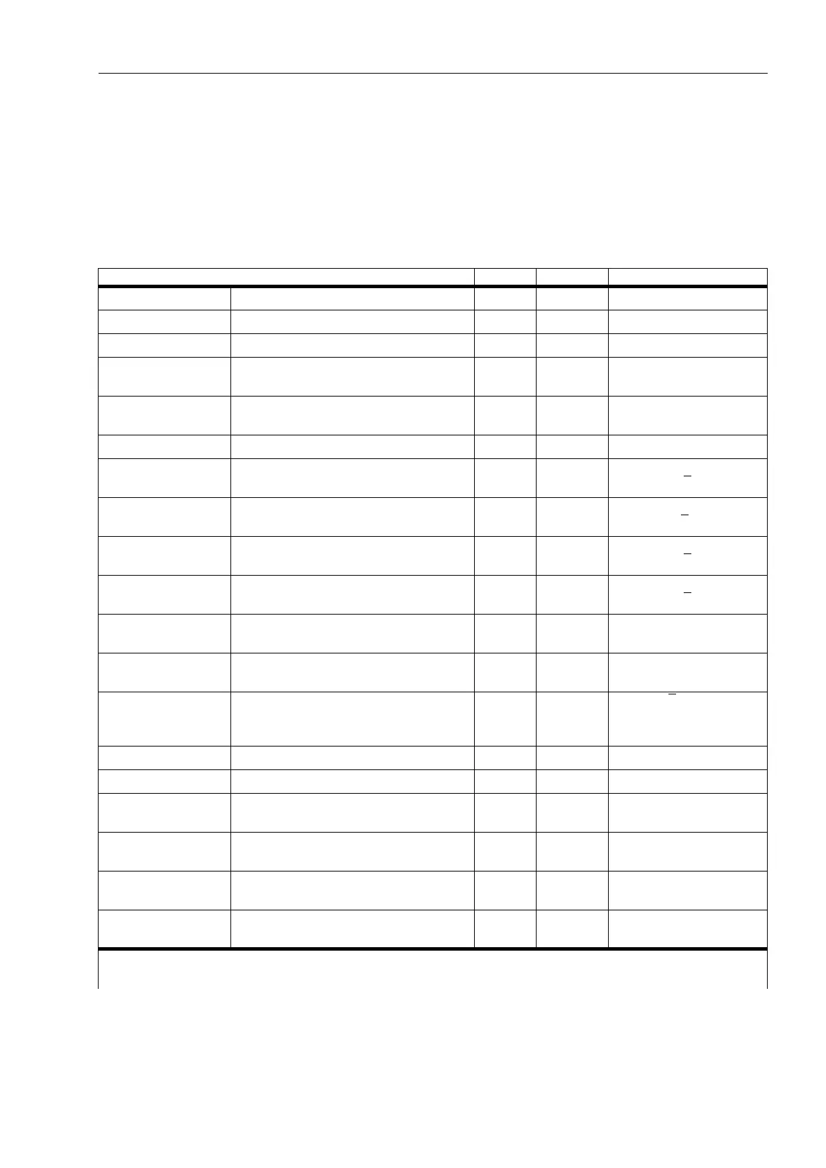
Table 6-15 Operational measured values
Measured values primary secondary % in relation to
I
L1
, I
L2
, I
L3
phase currents A A rated operational current
1
)
3I
0
earth currents A A rated operational current
1
)
I
1
, I
2
pos. and neg. seq. currents A A rated operational current
1
)
3I0
sen
sensitive earth current A mA rated operational current
1
)
3
)
I
Y
, I
P
transformer star point current or
earth current in the parallel line
A A rated operational current
1
)
3
)
U
L1–L2
, U
L2–L3
, U
L3–L1
line voltages kV V rated operational voltage
2
)
U
L1–E
, U
L2–E
, U
L3–E
phase-earth voltages kV V rated operational voltage /
√3
2
)
3U
0
displacement voltage kV V rated operational voltage
·√3
2
)
4
)
U
X
voltage at the measuring input U
4
kV V rated operational voltage /
√3
2
)
U
1
, U
2
pos. and neg. seq. voltages kV V rated operational voltage /
√3
2
)
R
L1–E
, R
L2–E
, R
L3–E
R
L1–L2
, R
L1–L2
, R
L3–L1
operational resistances
of all conductor loops
ΩΩ —
X
L1–E
, X
L2–E
, X
L3–E
X
L1–L2
, X
L2–L3
, X
L3–L1
operational reactances
of all conductor loops
ΩΩ —
S, P, Q apparent, real, and reactive power MVA,
MW,
MVAR
—
√3·U
N
·I
N
rated operational values
1
)
2
)
cos
ϕ power factor (abs) (abs) —
f frequency Hz Hz rated frequency
Θ
L1
/Θ
trip
, Θ
L2
/Θ
trip
,
Θ
L3
/Θ
trip
thermal value of each line
related to trip value
— — overtemperature
Θ/Θ
trip
thermal value, related to trip value,
calculated acc. to the configured method
— — overtemperature
U
line
, U
sync
, U
diff
line voltage, busbar voltage and voltage
magnitude difference (for synchro-check)
kV — —
f
line
, f
sync
, f
diff
line voltage, busbar voltage and frequency
difference (for synchronism check)
Hz — —
1
) acc. to address (refer to Sub-section 6.1.3)
2
) acc. to address (refer to Sub-section 6.1.3)
3
) with consideration of the factor ,,SK&7 (refer to Sub-section 6.1.1)

 Loading...


