Appendix
A-4 7SA6 Manual
C53000-G1176-C133-1
Version
Distance Protection with 4-line display) 1
Distance Protection with graphic display and control keys (integrated) 3
Type of Device
Distance Protection, medium voltage / high voltage, housing size
1
/
1
x 19“ 2
Measured Current Inputs (4 x U, 4 x I)
Iph = 1 A, Ie = 1 A (min. = 0.05 A) 1
Iph = 1 A, Ie = sensitive (min. = 0.005 A) 2
Iph = 5 A, Ie = 5 A (min. = 0.25 A) 5
Iph = 5 A, Ie = sensitive (min. = 0.005 A) 6
Auxiliary Voltage (Power Supply, Pick-up Threshold of Binary Inputs)
DC 24 V to 48 V, Threshold Binary Input 17 V
2
)2
DC 60 V to 125 V
1
), Threshold Binary Input 17 V
2
)4
DC 110 V to 250 V
1
), AC 115 V, Threshold Binary Input 73 V
2
)5
Housing / Number of Binary Inputs (BI) and Outputs (BO)
BI = Binary Inputs, BO: = Binary Outputs
Flush mounting housing,
1
/
1
x 19“, 21 BI, 24 BO (7 fast), 1 Live status contact A
Flush mounting housing,
1
/
1
x 19“, 29 BI, 32 BO (7 fast), 1 Live status contact B
Flush mounting housing,
1
/
1
x 19“, 33 BI, 11 BO, 8 (4) Power Relay, 1 Live status contact C
Surface mounting housing,
1
/
1
x 19“, 21 BI, 24 BO (7 fast), 1 Live status contact E
Surface mounting housing,
1
/
1
x 19“, 29 BI, 32 BO (7 fast), 1 Live status contact F
Surface mounting housing,
1
/
1
x 19“, 33 BI, 11 BO, 8 (4) Power Relay, 1 Live status contact G
Flush mounting housing with plug-in terminals,
1
/
1
x 19“, 21 BI, 24 BO (7 fast), 1 Live status contact J
Flush mounting housing with plug-in terminals,
1
/
1
x 19“, 29 BI, 32 BO (7 fast), 1 Live status contact K
Flush mounting housing with plug-in terminals,
1
/
1
x 19“, 33 BI, 11 BO, 8 (4) Power Relay, 1 Live status contact L
8 (4) Power Relay: 8 Power Relay (can only be used in pairs)
1) with plug-in jumper one of the 2 voltage ranges can be selected
2) for each binary input one of 2 pick-up threshold ranges can be selected with plug-in jumper
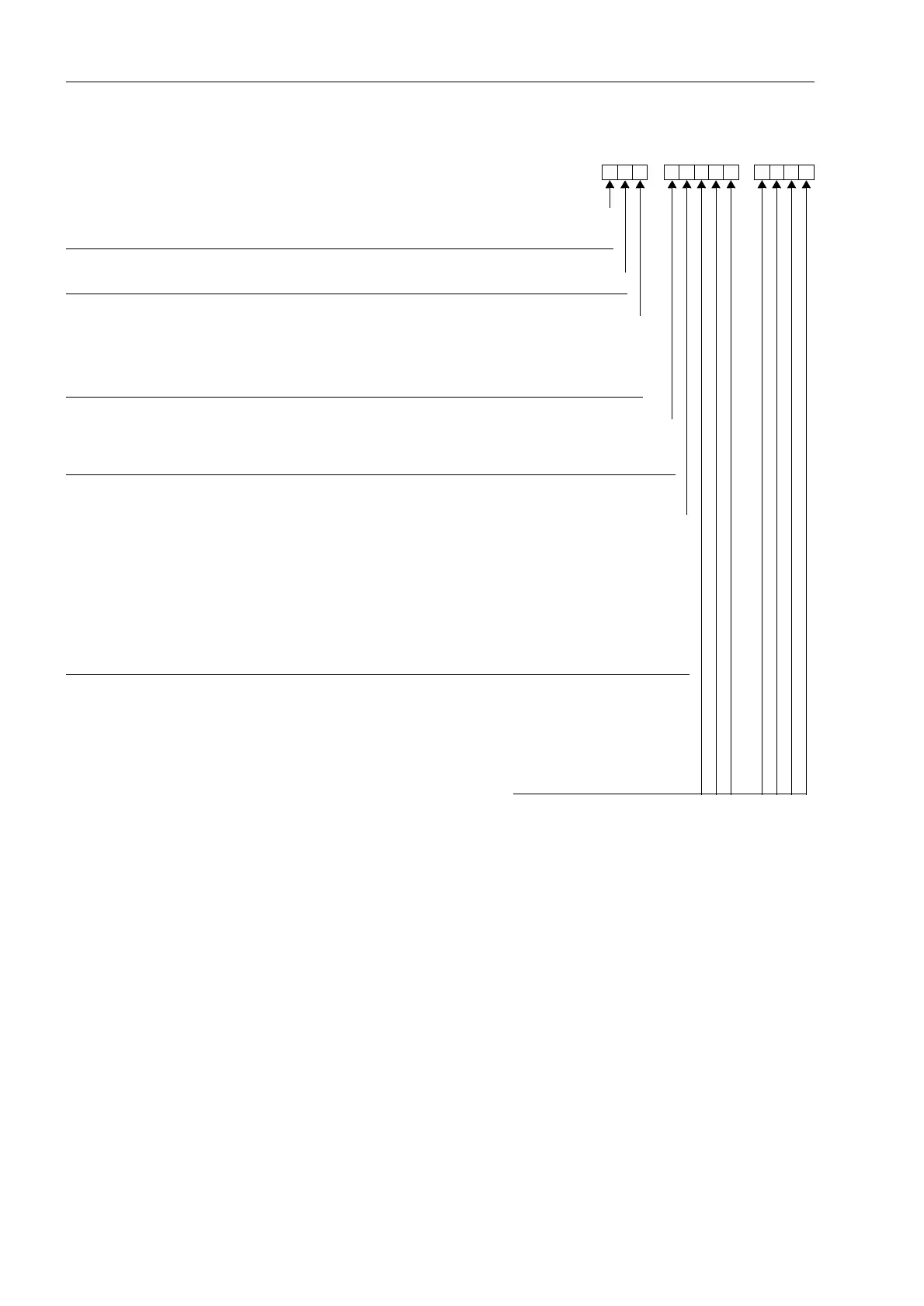
For details on positions 10 to 16 see page A-7 and A-8
_
7SA6
7 8 13 15 1614
_
9101112
Digital Distance Protection (position 1 to 9)
6
5

 Loading...


