Cabinet Modules
5.7 Auxiliary Power Supply Modules
Cabinet Modules NEMA
Manual, 04/2014, A5E03586450A
245
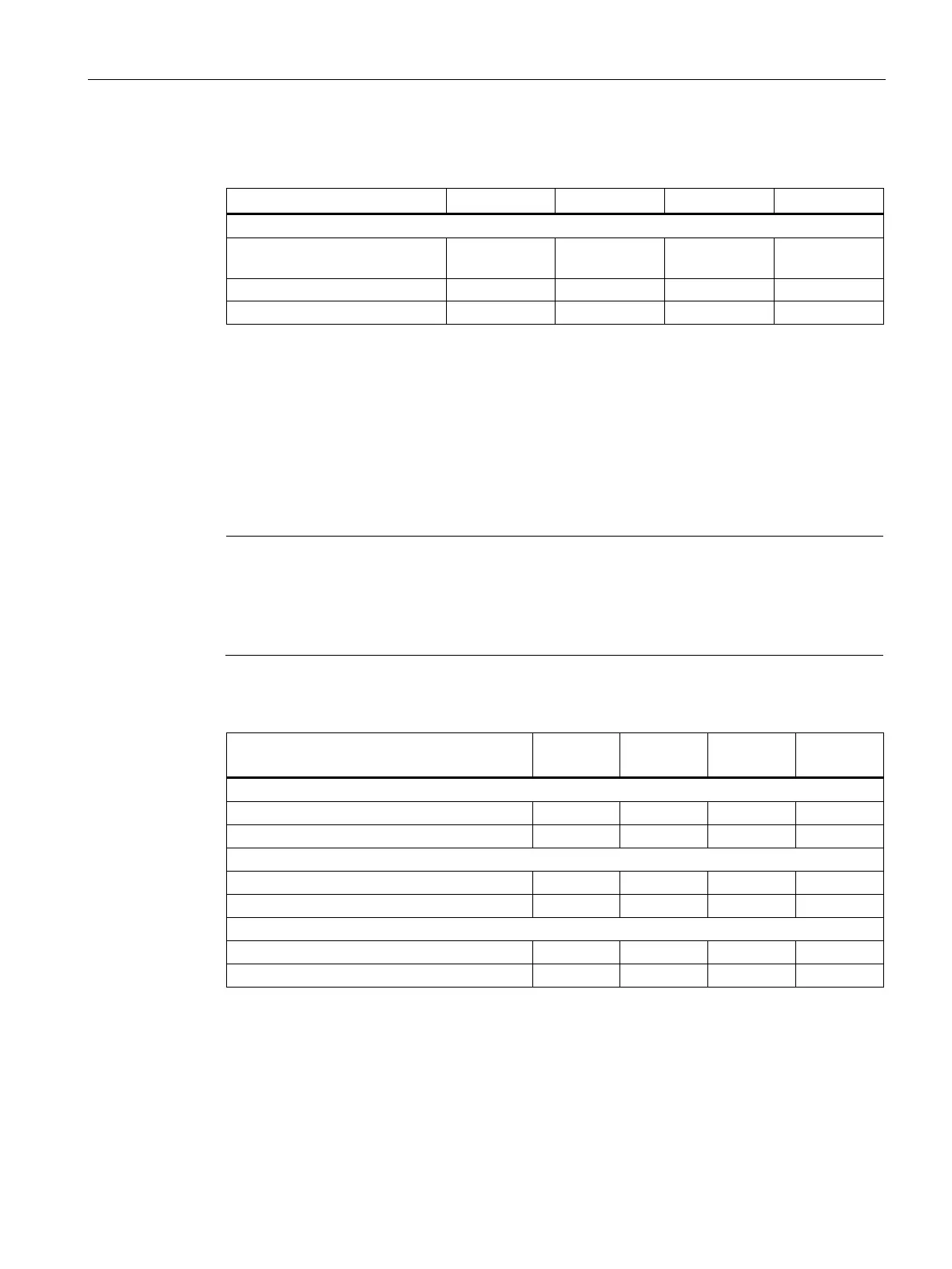
Table 5- 43 Overview of the fuses for the auxiliary power supply system in the Auxiliary Power Sup-
ply Module
380 to 690 V 2 ph. AC (depend-
ing on the rated device voltage)
63 80 80 80
Customer interfaces for supplying power to an additional auxiliary power supply
system
This section describes only those interfaces in the cabinet that require additional connection
work by the customer. All other interfaces are pre-wired at the factory and are not designed
for customer connections. The table below provides an overview of the most important
technical data of the customer terminals in the cabinet.
Note
Additional information
All connections to be established on the plant side as well as the interfaces for integration
into the plant control system are described in the circuit and terminal diagrams on the
customer DVD supplied.
Table 5- 44 Overview of customer terminals in the auxiliary power supply module
Cabinet Module
Order no. 6SL3700-
Customer terminal -X45 for tapping the line voltage (380 to 480 V 3 ph. AC or 500 to 690 V 3 ph. AC)
1)
Max. conductor cross-section in AWG (mm
2
Customer terminal -X46 for connection of an uninterruptible power supply for SITOP
2)
3)
Max. conductor cross-section in AWG (mm
2
Customer terminal -X47 for tapping the 230 V 1 ph. AC voltage
Max. conductor cross-section in AWG (mm
2
The fuse protection is implemented via the circuit-breaker -Q4, the specified currents correspond
to the factory setting.
When an uninterruptible power supply is connected, the jumpers between -X46:1/2 and -X46:5/6
must be removed.
The customer is responsible for providing external fuse protection for the uninterruptible power
supply according to the specifications for the 24 V DC power supply used.
 Loading...


