Options
8.20 K90, Control Unit CU320-2 DP
Cabinet Modules NEMA
404 Manual, 04/2014, A5E03586450A
X41 EP terminal / temperature sensor connection
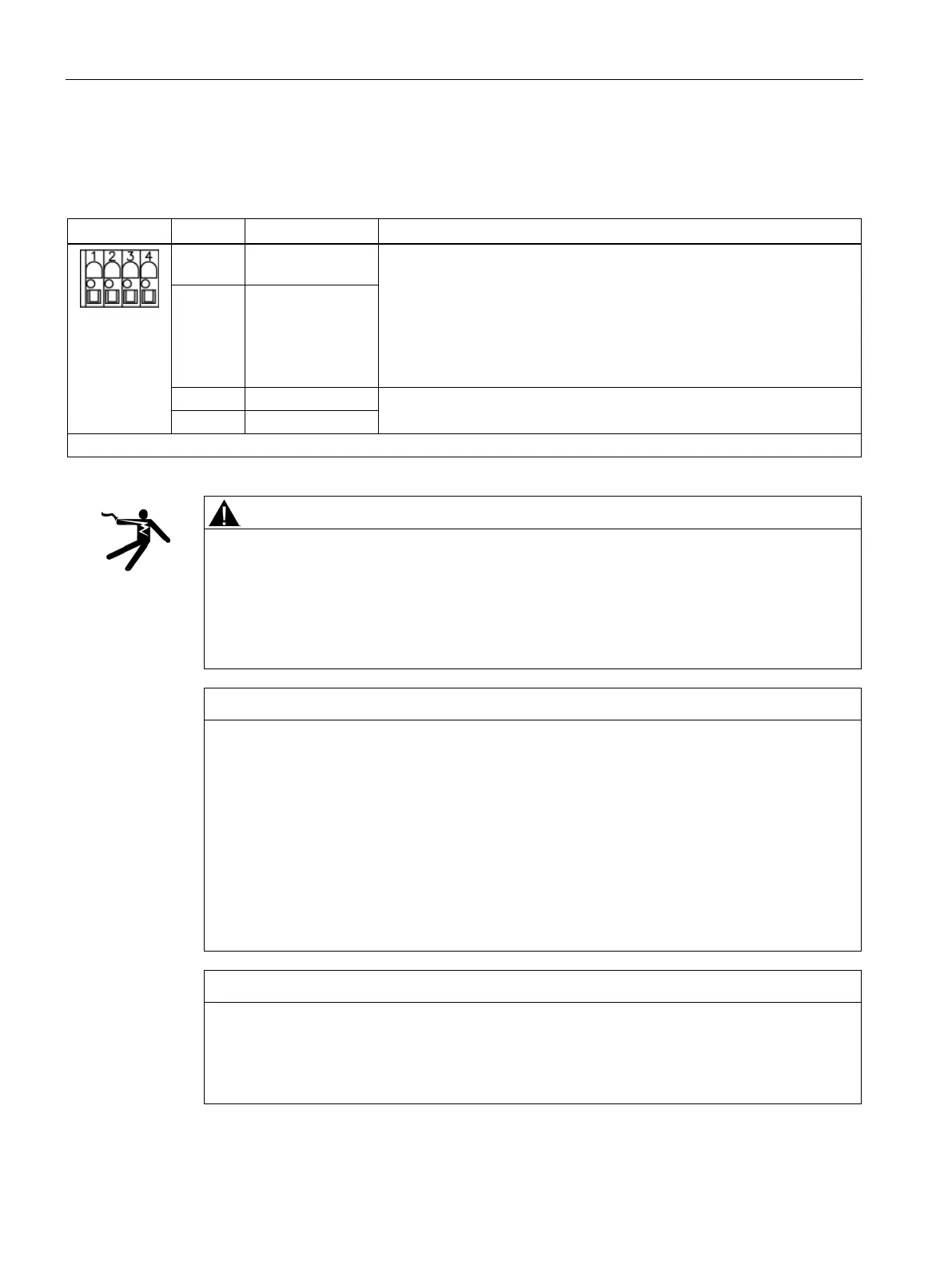
Table 8- 18 Terminal block X41 on the customer terminal block X55
1 EP M1
Supply voltage: 24 V DC (20.4 to 28.8 V)
Current consumption: 10 mA
Signal propagation times:
L → H: 100 μs;
H → L: 1000 μs
The pulse inhibit function is only available when Safety Integrated Basic
2 EP +24 V
(enable pulses)
Temperature sensor connection for motor temperature measurement:
KTY84-1C130, PTC, PT100, bimetallic switch with NC contact
Max. connectable cross-section: #14 AWG (2.5 mm
2
Risk of death from electric shock in the event of voltage flashovers at the temperature
sensor
Voltage flashovers in the signal electronics can occur in motors without safe electrical
separation of the temperature sensors.
• Only use temperature sensors that fully comply with the specifications of the electrical
separation.
Device failure due to unshielded or incorrectly routed cables to temperature sensors
Unshielded or incorrectly routed cables to temperature sensors can result in interference
being coupled into the signal processing electronics from the power side. This can result in
significant disturbance of all signals (fault messages) up to failure of individual components
(destruction of the devices).
• Only use shielded cables as temperature sensor cables.
• If temperature sensor cables are routed together with the motor cable, use twisted-pair,
separately-shielded cables.
• Connect the cable shield at both ends to ground potential over a large surface area.
• Recommendation: Use suitable Motion Connect cables.
Risk of motor overheating due to incorrectly connected KTY temperature sensor
A KTY temperature sensor connected with incorrect polarity cannot detect if the motor
overheats.
• Make sure that you connect the KTY temperature sensor with the correct polarity.
 Loading...


