Maintenance and servicing
6.4 Replacing components
Cabinet Modules NEMA
256 Manual, 04/2014, A5E03586450A
The components required for connecting the DC busbars to the power unit are supplied as
standard. If components were replaced, you may have to restore these connections. The
connection procedure is described in the following section.
Preparatory steps:
● Disconnect the cabinet from the power supply (do not forget the external power supplies).
● Allow unimpeded access to the DC busbars
(if necessary, remove the protective covers during installation work)
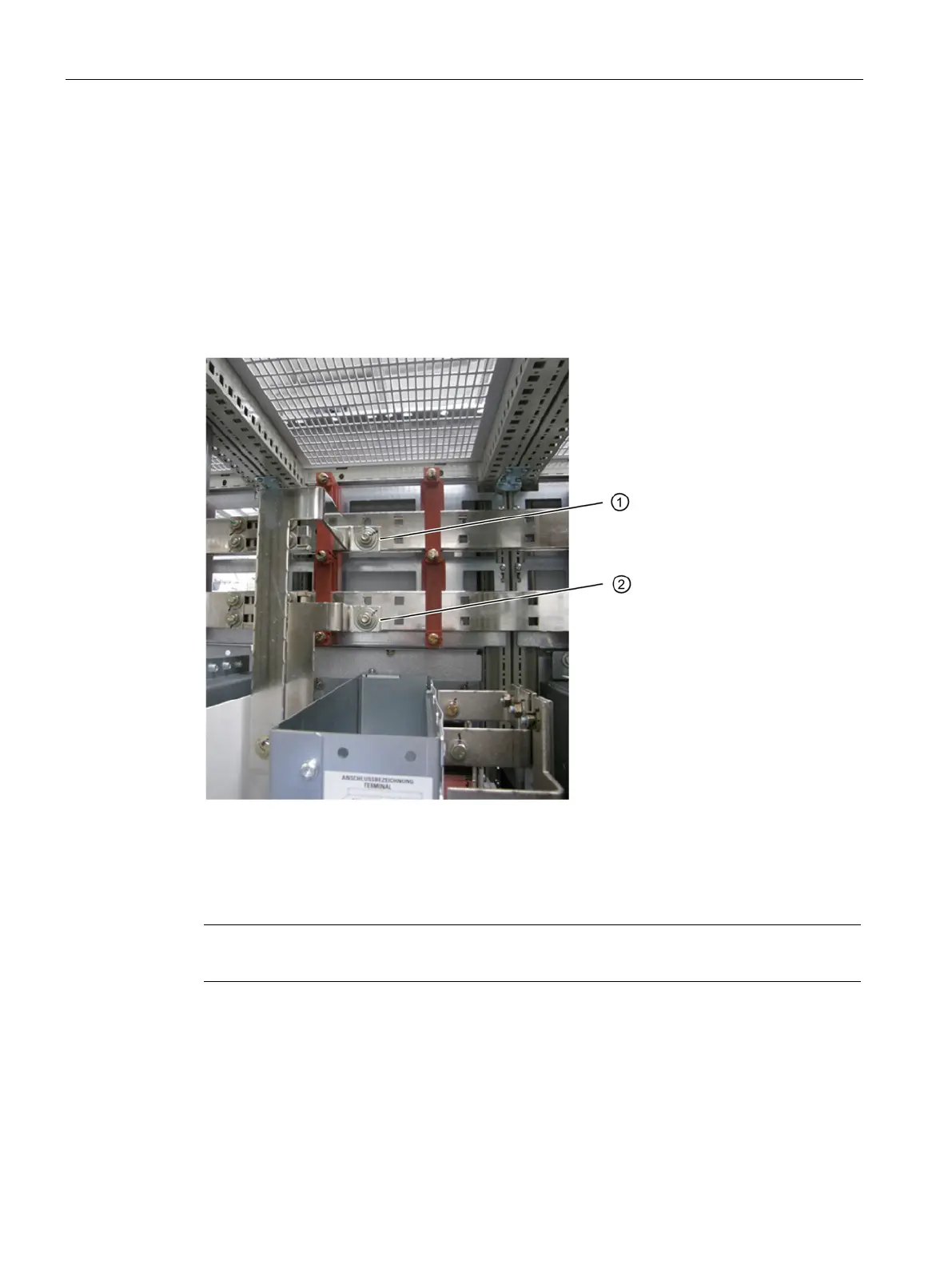
Figure 6-3 Connection to the DC busbar on the Basic Line Module, Smart Line Module, Active Line
Module and Motor Module in the chassis format
Establishing the connection for booksize format
Note
Make sure that you do not drop any nuts, washers, or screws as this could cause damage.
1. Connect the "DC P" connection on the Motor Module to the upper DC busbar (DC P) (1 x
M12 screw + nut + washer; torque: 50 Nm).
2. Connect the "DC N" connection on the Motor Module to the lower DC busbar (DC N) (1 x
M12 screw + nut + washer; torque: 50 Nm).
 Loading...


