Options
8.20 K90, Control Unit CU320-2 DP
Cabinet Modules NEMA
Manual, 04/2014, A5E03586450A
411
The first and last nodes in a bus must contain terminating resistors. Otherwise, data
transmission will not function correctly.
The bus terminating resistors are activated in the connector.
The cable shield must contact at both ends with the greatest possible surface area.
PROFIBUS address switches
The PROFIBUS address is set as a hexadecimal value via two rotary coding switches.
Values between 0
dec
(00
hex
) and 127
dec
(7F
hex
) can be set as the address. The high rotary
coding switch (H) is used to set the hexadecimal value for 16
1
, and the low rotary coding
switch (L) is used to set the hexadecimal value for 16
0
.
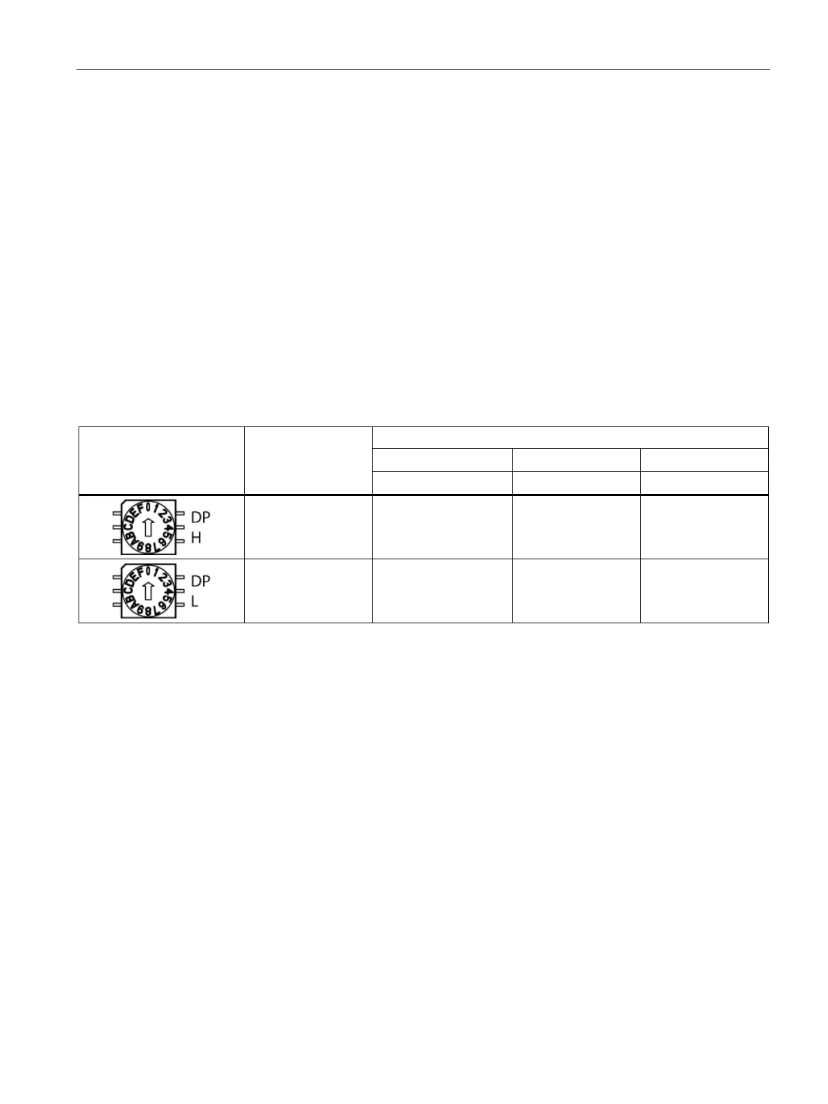
Table 8- 24 PROFIBUS address switches
16
1
= 16 1 2 7
16
0
= 1 5 3 E
Setting the PROFIBUS address
The factory setting for the rotary coding switches is 0
dec
(00
hex
).
There are two ways to set the PROFIBUS address:
1. Via the parameter p0918
– To set the bus address for a PROFIBUS node using STARTER, first set the rotary
coding switches to 0
dec
(00
hex
) and 127
dec
(7F
hex
).
– Then use parameter p0918 to set the address to a value between 1 and 126.
2. Via the PROFIBUS address switch on the control unit
– The address is set manually to values between 1 and 126 using the rotary coding
switches. In this case, p0918 is only used to read the address.
The address switch is behind the blanking plate. The blanking plate is part of the scope of
supply.
 Loading...


