Electrical installation
4.5 Connections
Cabinet Modules NEMA
90 Manual, 04/2014, A5E03586450A
Adjusting the fan voltage
A transformer is incorporated in the Motor Module in the chassis format (-T1-T10) and/or
Basic Line Module/Smart Line Module/Active Line Module (-T2-T10) for setting the correct
operating voltage for the 230 V AC fans. The location of the transformers is indicated in the
layout diagrams supplied.
The transformer is fitted with primary taps so that it can be adapted to the line voltage. When
delivered, the taps are always set to the highest level. When connected to a lower line
voltage, the appropriate transformer tap must be used. The neutral conductor is left on
terminal "0" and the phase is clamped to the existing line voltage.
The fans are designed for 50/60 Hz operation.
Note
Positions of the setting terminals
The position of the setting terminals for the fan transformers is provided in section "Cabinet
Mo
dules" in the design descriptions of the appropriate modules.
Note
Two transformers for frame sizes HX and JX
Two transformers (
-T10/-T11) are installed in the case of Smart Line Modules, Active Line
Modules, and Motor Modules with "HX" and "JX" frame
sizes. The two primary terminals of
these devices must be adjusted together.
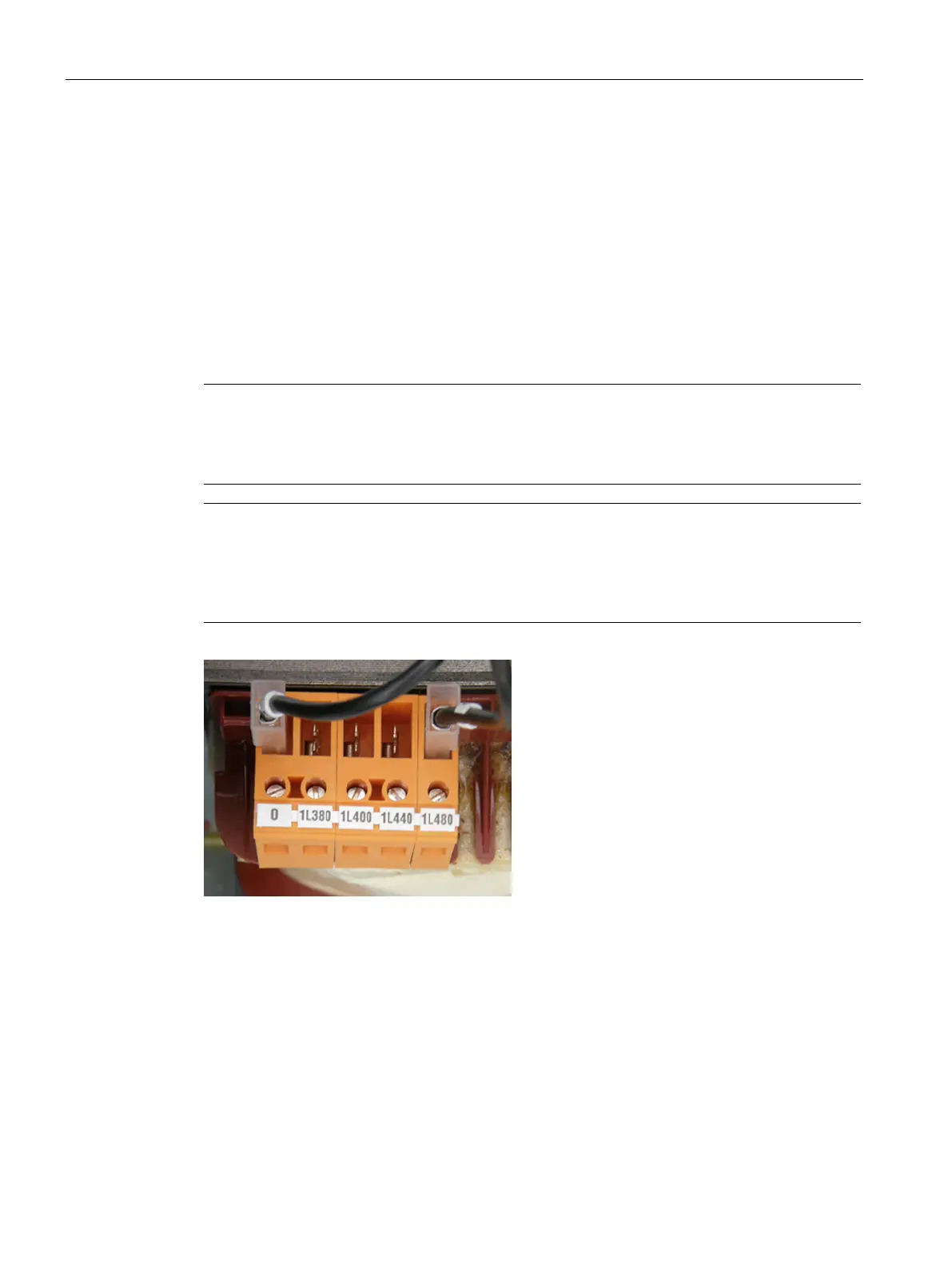
Figure 4-11 Connecting terminals for the fan transformers (380 to 480 V 2 ph. AC)
 Loading...


