System overview
2.11 Derating data
Cabinet Modules NEMA
Manual, 04/2014, A5E03586450A
41
Use of an isolation transformer to reduce transient overvoltages
As a consequence, overvoltage category III is reduced to overvoltage category II – which in
turn reduces the demands placed on the insulating capability of air. An additional voltage
derating (reduction of the input voltage) is not required if the following secondary conditions
are maintained:
● The isolation transformer must be fed from a low-voltage supply or a medium-voltage
supply and must not be directly supplied from a high voltage supply.
● The isolation transformer may supply one or several Line Modules.
● The cables between the isolation transformer and the Line Module or Line Modules must
be routed so that a direct lightning strike is completely ruled out, i.e. cables must not be
routed outside.
● The following line supply types are permissible for drives equipped with Basic Line
Modules and Smart Line Modules:
– TN line supplies with grounded star point (no grounded phase conductor).
– IT line supplies (operation with a short circuit must be restricted to the absolutely
shortest possible time).
● The following line supply types are permissible for drives equipped with Active Line
Modules:
– TN provider networks with grounded star point (no grounded phase conductor, no IT
systems) for installation altitudes above 6,600 ft (2,000 m).
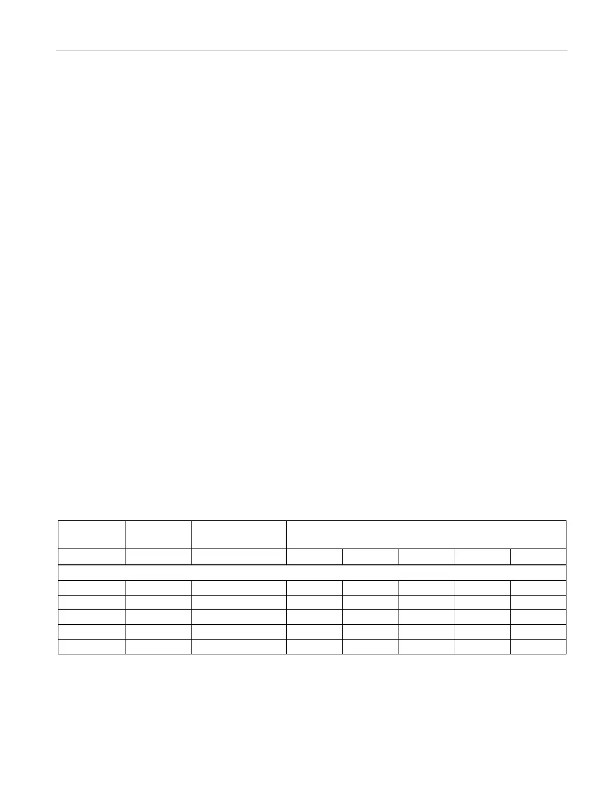
Current derating depending on the pulse frequency
When the pulse frequency is increased, the derating factor of the output current must be
taken into account. This derating factor must be applied to the currents specified in the
technical data for Motor Modules.
Table 2- 7 Derating factor of the output current as a function of the pulse frequency for devices with a rated pulse fre-
quency of 2 kHz
Derating factor at the pulse frequency
Supply voltage 510 – 720 VDC
1TE33-8AU3 300 (200) 380 96 % 87 % 77 % 54 % 50 %
 Loading...


