Options
8.22 K95, CU320-2 PN Control Unit
Cabinet Modules NEMA
430 Manual, 04/2014, A5E03586450A
X132 digital inputs/outputs
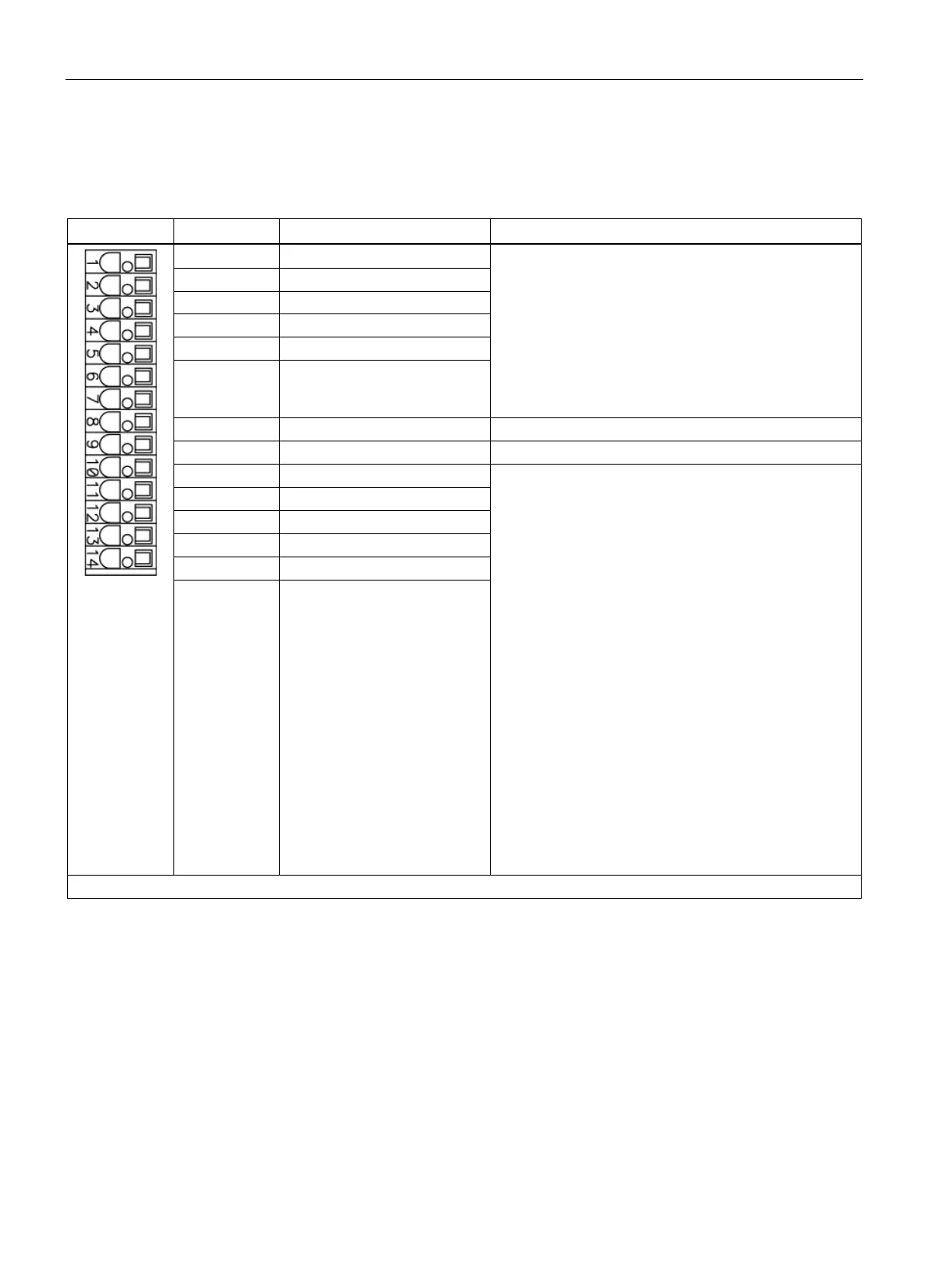
Table 8- 32 Terminal block X132 on the customer terminal block X55
Voltage (max.): -30 to +30 V DC
Typical power consumption: 9 mA at 24 V
Electrical isolation: reference potential is terminal M2
Level (including ripple)
High level: 15 ... 30 V
Low level: -30 ... +5 V
Input delay (typ.):
For "0" → "1": 50 μs
2 DI 5
4 DI 7
6 DI 21
Reference potential for terminal 1 ... 6
:
Voltage: -30 to +30 V DC
Typical power consumption: 9 mA at 24 V
Level (including ripple)
High level: 15 ... 30 V
Low level: -30 ... +5 V
DI/DO 12, 13, 14, and 15 are "rapid inputs"
2)
Input delay (typ.):
For "0" → "1": 5 μs
For "1" → "0": 50 μs
:
Voltage: 24 V DC
Max. load current per output: 500 mA
Continuous short circuit-proof
Output delay (typ./max.)
3)
:
For "0" → "1": 150 μs / 400 μs
For "1" → "0": 75 μs / 100 μs
Switching frequency:
For resistive load: Max. 100 Hz
For inductive load: Max. 0.5 Hz
For lamp load: Max. 10 Hz
14 M
Max. connectable cross-section: #14 AWG (2.5 mm
2
DI: Digital input; DI/DO: Digital input/output; M: Electronics ground; M2: Ground reference
The rapid inputs can be used as probe inputs or as inputs for the external zero mark
3)
Data for: V
cc
= 24 V; load 48 Ω; high ("1") = 90 % V
out
; low ("0") = 10 % V
out
The maximum cable length that can be connected is 99 ft (30 m).
 Loading...


