Options
8.34 L61/L62, L64/L65, braking units
Cabinet Modules NEMA
464 Manual, 04/2014, A5E03586450A
Commissioning/configuration
If a Control Unit is not being used (option K90/K95), then the four signals of terminal block -
X55-X132 must be wired to the corresponding Control Unit or to the customer interface -X55.
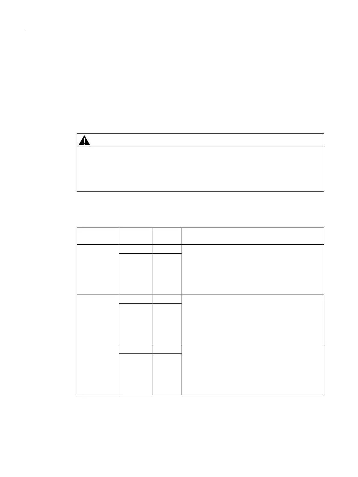
The response threshold at which the braking module is activated and the DC link voltage
generated during braking is specified in the following table.
Risk of death from electric shock when operating the threshold switch
Operating the threshold switch when a voltage is present can cause death or serious injury.
• Operate the threshold switch only when the Basic Line Module, Smart Line Module,
Active Line Module, or Motor Module are switched off and the DC link capacitors are
discharged.
Table 8- 54 Response thresholds of the braking modules
380 to 480 V 3
ph. AC
774 V is the default factory setting. For line voltages of
380 ... 400
V 3 ph. AC, the response threshold can be set
to 673 V to reduce the voltage stress on the motor and
converter. However, this reduces the possible braking
power to the square of the voltages (673/774)² = 0.75.
Therefore, the maximum available braking power is 75
774 V 2
500 to 600 V 3
ph. AC
967 V is the default factory setting. With a line voltage of
500 V 3 ph. AC, the response threshold can be set to
841 V to reduce the voltage stress on the motor and
converter. However, this reduces the possible braking
power to the square of the voltages (841/967)² = 0.75.
Therefore, the maximum available braking power is 75
967 V 2
660 ... 690 V 3
ph. AC
1158 V is the default factory setting. With a line voltage of
660 V 3 ph. AC, the response threshold can be set to
1070 V to reduce the voltage stress on the motor and
converter. However, this reduces the possible braking
power to the square of the voltages (1070/1158)² = 0.85.
Therefore, the maximum available braking power is 85
1158 V 2
 Loading...


