Options
8.46 M80 to M87, DC busbar system
Cabinet Modules NEMA
Manual, 04/2014, A5E03586450A
493
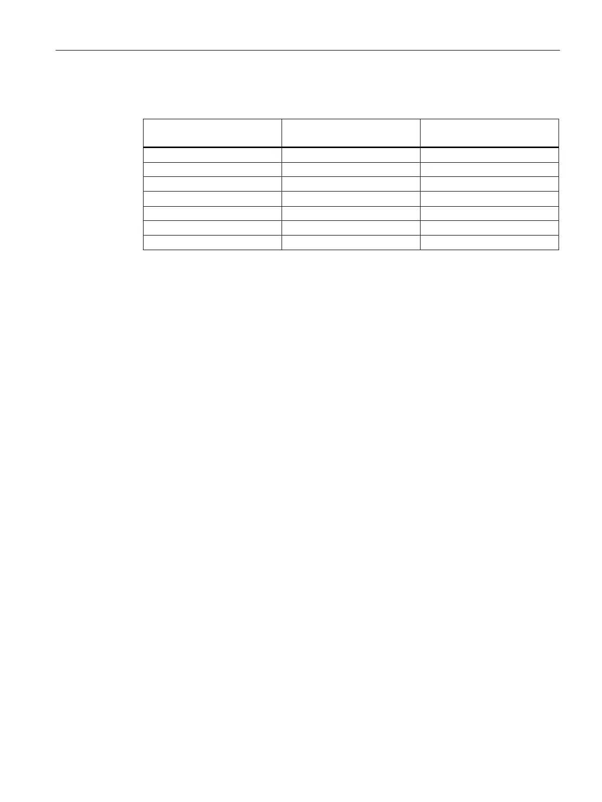
Table 8- 64 Conductor cross-section when connecting motor cables directly to the Booksize Motor
Module
Conductor cross-section in mm²
(AWG)
1TE24-5AB0 24 (30) 6 ... 50 (10 ... 1)
1TE28-5AB0 46 (60) 16 ... 120 (6 ... 5/0)
M80 to M87, DC busbar system
Availability of option
This option is available for the following S120 Cabinet Modules:
● Line Connection Modules
● Basic Line Modules
● Smart Line Modules
● Active Line Modules
● Booksize base cabinets
● Motor Modules chassis
● Auxiliary Power Supply Modules
The DC busbar connects the DC voltage across the drive assembly. The DC busbar
comprises an upper busbar (DC P) and a lower busbar (DC N).
The following optional DC busbars are available:
● Option M80 = busbar system 1 x 60 x 10
● Option M81 = busbar system 1 x 80 x 10
● Option M82 = busbar system 1 x 100 x 10
● Option M83 = busbar system 2 x 60 x 10
● Option M84 = busbar system 2 x 80 x 10
● Option M85 = busbar system 2 x 100 x 10
● Option M86 = busbar system 3 x 80 x 10
● Option M87 = busbar system 3 x 100 x 10
 Loading...


