Options
8.20 K90, Control Unit CU320-2 DP
Cabinet Modules NEMA
Manual, 04/2014, A5E03586450A
401
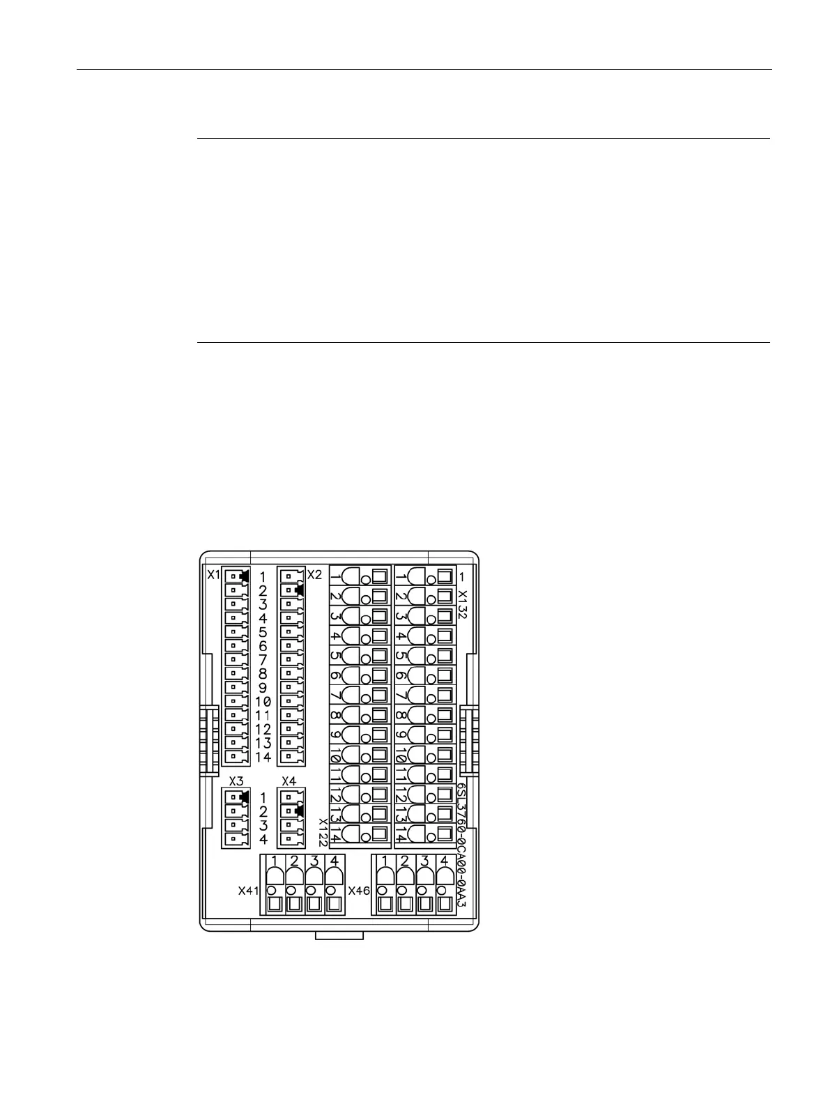
Note
Power supply for the digital inputs
In the circuit example, the power for the dig
ital inputs (terminals -X122 and -X132) is
supplied from the internal 24 V voltage of the Control Unit (terminal
-X124).
The two groups of digital inputs (optocoupler inputs) each have a common reference
potential (reference ground M1 or M2). To close the
circuit when the internal 24 V supply is
used, the reference grounds M1 / M2 are connected to internal ground (M).
If power is not supplied from the internal 24 V supply (terminal
-X124), the jumper between
grounds M1 and M or M2 and M must be removed in o
rder to avoid potential current loops.
The external ground must then be connected to terminals M1 and M2.
X55 customer terminal block
8.20.4.1
Figure 8-27 Option G55, customer terminal block -X55
 Loading...


