Electrical installation
4.5 Connections
Cabinet Modules NEMA
92 Manual, 04/2014, A5E03586450A
Table 4- 13 Line voltage assignments for setting the fan transformer (500 to 690 V 2 ph. AC)
Taps of the fan transformer (-T1/-T2 -T10, -T20)
600 V ± 10 % 600 V
Connecting Cabinet Modules to an ungrounded / IT power networks
If the Cabinet Modules are operated on an ungrounded system (IT system), the integrated
basic interference suppression modules must be deactivated by unscrewing the connection
clip in the following Cabinet Modules:
● Basic Line Modules
● Smart Line Modules
(the connection clip is located behind the fan for frame sizes HX and JX)
● Active Line Modules (connection clip in the Active Interface Module)
Device damage resulting from failure to remove the connection clip on an ungrounded
system
Failure to remove the connection clip to the basic interference suppression module on an
ungrounded system (IT system) can cause significant damage to the device.
• On an ungrounded system (IT system), remove the connection clip to the basic
interference suppression module.
Note
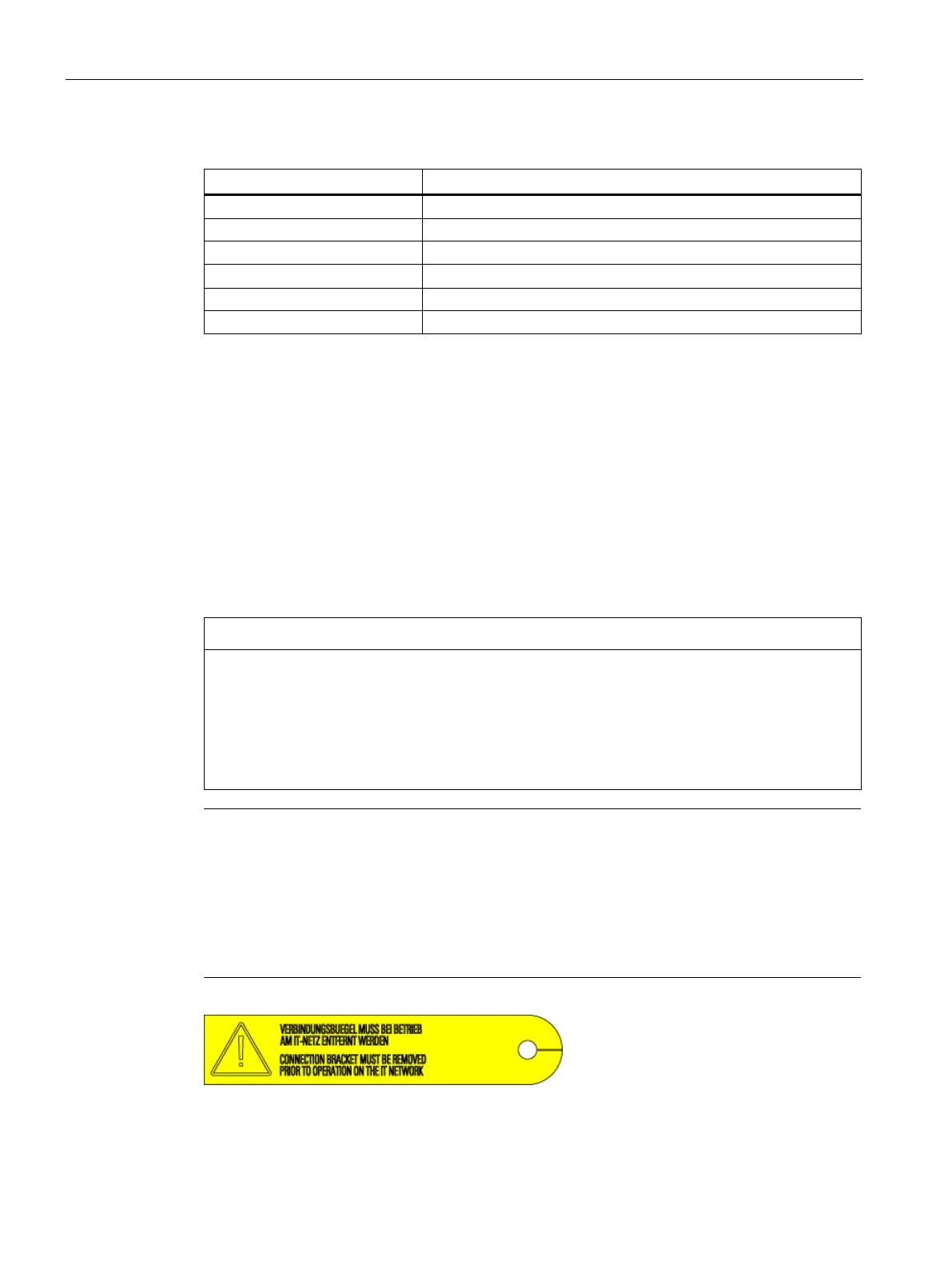
Warning label on the connection clip
A yellow warning label is attached to each connection clip so that it is easier to find.
The warning label must be removed from the connection clip (by pulling it off) if the
connection clip is to remain in the unit (operation on a grounded system).
The warning label must be removed together with the connection clip if the unit is
operated on an ungrounded system (IT system).
Figure 4-13 Warning label on the connection clip
 Loading...


