Cabinet Modules
5.7 Auxiliary Power Supply Modules
Cabinet Modules NEMA
Manual, 04/2014, A5E03586450A
247
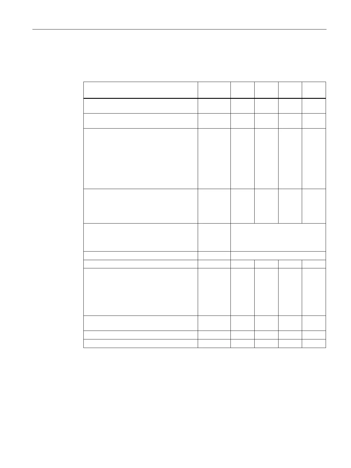
Table 5- 45 Technical specifications for the Auxiliary Power Supply Modules
Plant side supply
380 to 690 V 3 ph. AC
- Cable cross-section, max. (IEC)
2
Current carrying capacity, max.
- Load feeder connection 380 to 690 V AC
- at the auxiliary power supply system
1)
- at customer terminal -X45
- Load feeder connection 230 V AC
- at the auxiliary power supply system
- at customer terminal -X47
- Load feeder connection 24 V DC
- at the auxiliary power supply system
A
A
A
A
63
50
6
8
80
63
10
10
80
80
10
10
80
80
20
20
Cable cross-section, max.
- connection -X45
- connection X47
- connection -X45
AWG
AWG
mm
2
2
6
14
16
6
14
16
6
14
16
6
14
16
- Busbar cross-section
- Max. conductor cross-section (IEC)
- Max. conductor cross-section (NEC, CEC)
mm
2
mm
2
PE busbar
600
240
Degree of protection (standard model)
(standard model, IP20)
- width
- height
2)
- depth
- width
- height
2)
inch
inch
inch
mm
mm
23.6
86.6
23.6
600
2200
23.6
86.6
23.6
600
2200
23.6
86.6
23.6
600
2200
23.6
86.6
23.6
600
2200
(standard model) lb
375
397
463
530
SCCR (short circuit current rating)
Minimum short-circuit current
2)
The fuse protection is implemented via the circuit-breaker -Q3, the specified currents correspond
to the factory setting.
The cabinet height increases by 10" (250 mm) with degree of protection IP21, and by 16" (400
mm) for degrees of protection IP23 (NEMA1 filtered), IP43 and IP54 (NEMA12 ventilated).
2)
Current required for reliable tripping of the contained protective devices.
 Loading...


