Diagnostics
7.8 LEDs on the Control Interface Module in the Motor Module, chassis format
Cabinet Modules NEMA
Manual, 04/2014, A5E03586450A
341
LEDs on the Control Interface Module in the Motor Module, chassis
format
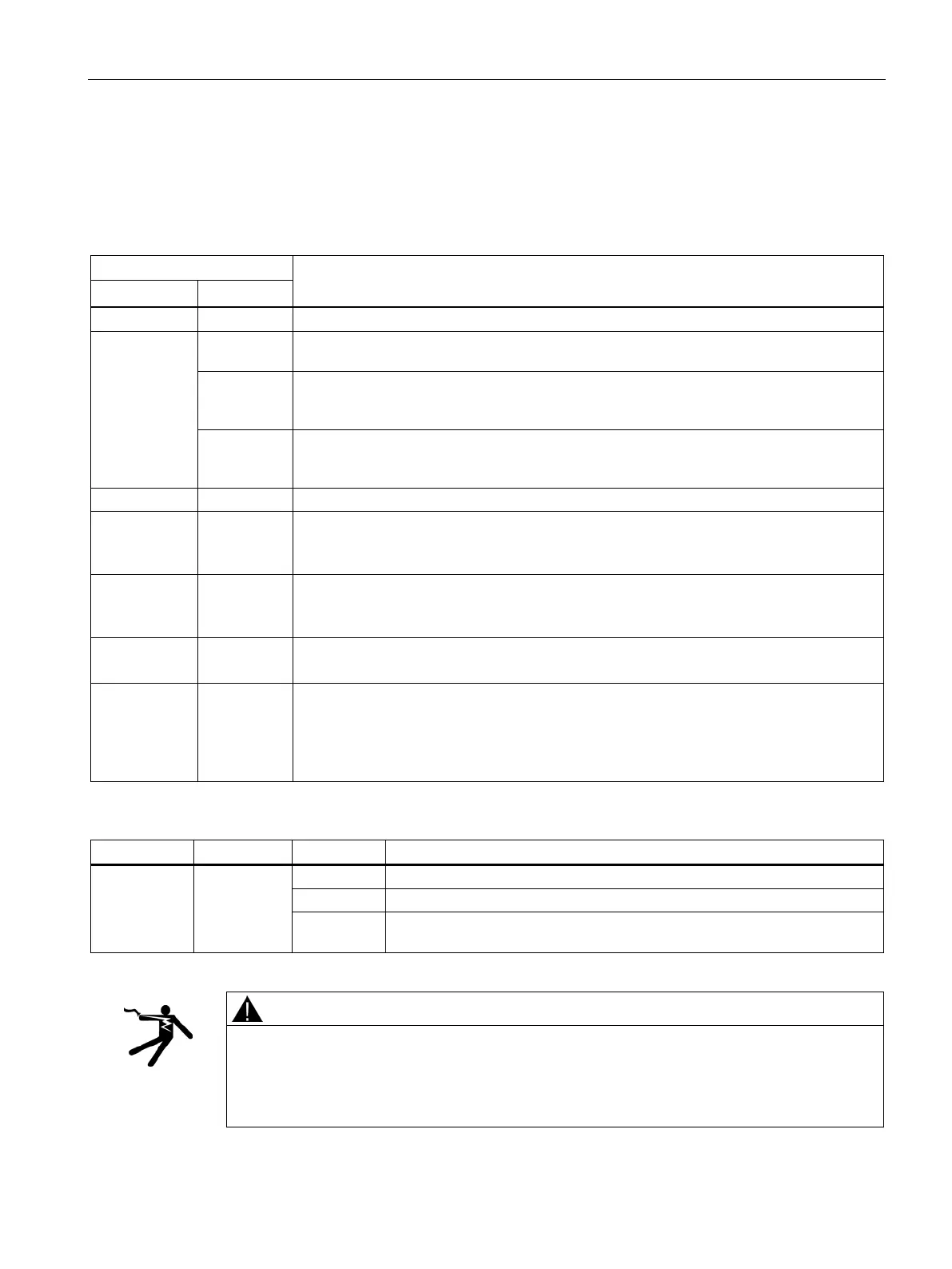
Table 7- 16 Meaning of the LEDs "READY" and "DC LINK" on the control interface module in the Motor Module
The electronics power supply is missing or lies outside the permissible tolerance range.
Green Off The component is ready for operation and cyclic DRIVE-CLiQ communication is taking
Orange The component is ready for operation and cyclic DRIVE-CLiQ communication is taking
place.
The DC link voltage is present.
Red The component is ready for operation and cyclic DRIVE-CLiQ communication is taking
place.
The DC link voltage is too high.
DRIVE-CLiQ communication is being established.
Red --- At least one fault is present in this component.
Note:
LED is activated irrespective of any reconfiguring of the corresponding messages.
Flashing
0.5 Hz:
--- Firmware is being downloaded.
Flashing 2 Hz:
--- Firmware download is complete. Waiting for POWER ON.
Flashing 2 Hz:
Green /
Orange
or
--- Detection of the component via LED is activated (p0124).
Note:
The two options depend on the LED status when component detection is activated via
p0124 = 1.
Table 7- 17 Meaning of the LED "POWER OK" on the control interface module in the Motor Module
POWER OK Green
DC link voltage < 100 V and voltage at -X9:1/2 less than 12 V.
The component is ready for operation.
Flashing There is a fault. If the LED continues to flash after you have performed a
POWER ON, please contact your Siemens service center.
Risk of death when live parts of the DC link are touched
Irrespective of the status of the "DC LINK" LED, hazardous DC link voltages can always be
present.
• Observe the warning information on the component.
 Loading...


