Home
Siemens
DC Drives
SIROTEC
Siemens SIROTEC Device Manual
4
of 1
of 1 rating
510 pages
Give review
Manual
Specs
To Next Page
To Next Page
To Previous Page
To Previous Page
Loading...
Maintenance
and ser
vicing
6.4
Repl
acing c
omponents
Cabinet Modules NEMA
Manual
,
04/2014
,
A5E03586450A
295
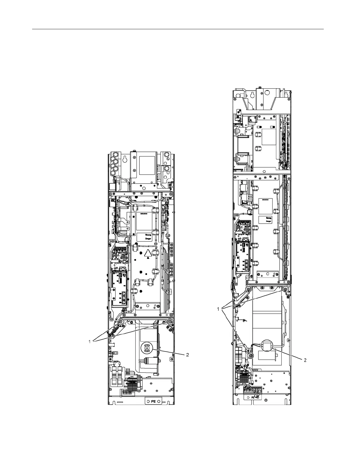
6.4.10.2
Replacing the fan, frame sizes FB, GB and GD
Replacing the f
an
Figure
6-
17
Replacing t
he fan,
Basic Line M
odule, frame sizes FB,
GB, and GD
294
296
Table of Contents
Default Chapter
5
Preface
5
Table of Contents
9
1 Basic Safety Instructions
17
General Safety Instructions
17
Safety Instructions for Electromagnetic Fields (EMF)
21
Handling Electrostatic Sensitive Devices (ESD)
21
Industrial Security
22
Residual Risks of Drive Systems
23
2 System Overview
25
Overview
25
Area of Application
27
Benefits
27
Line Modules
28
General Information
28
Basic Line Modules
28
Smart Line Modules
29
Active Line Modules
30
DC Link Components
32
Braking Modules as a Line Module or Motor Module Option
32
Motor Modules
32
Booksize Base Cabinets with Booksize Cabinet Kits
32
Chassis Cabinets
32
Auxiliary Power Supply Modules
32
System Structure
33
Overview of Options
33
System Data
36
Derating Data
38
Derating Data for Booksize Format
38
Derating Data for Chassis Format
38
General
38
Derating Measures
39
Current Derating Depending on the Pulse Frequency
41
3 Mechanical Installation
43
Important Notes
43
Mechanical Installation: Checklist
46
Installation
48
Important Safety Precautions
48
Preparation
48
Requirements for Installation Location
48
Requirements on the Levelness of the Floor
50
Shipping and Handling Indicators
51
Unpacking
53
Required Tools
54
Lifting the Cabinet Units off the Transport Pallet and Installing Them
55
Disassembling the Crane Transport Aids
56
Connection to the Foundation
58
Connection for Side-By-Side Installation of Cabinet Units
59
4 Electrical Installation
63
Safety Instructions
63
Checklist for Electrical Installation
64
EMC-Compliant Design
70
Connecting Shielded Three-Phase Cables
70
Connections
71
Cable Lugs
71
Connection Overview
72
PE Busbar
73
General Information
73
Connection for Side-By-Side Installation of Cabinet Units
73
Connection According to the System-Side Grounding Concept
75
Connecting External Cables to the PE Busbar
75
DC Busbar
75
General Information
75
Connection for Side-By-Side Installation of Cabinet Units
76
Auxiliary Power Supply System
78
General Information
78
Connection Overview
84
Connection for Side-By-Side Installation of Cabinet Units
84
Connecting to the Infeed
85
Connecting the Motor Cables
86
Line Supply Connections
89
Adjusting the Fan Voltage
90
Connecting Cabinet Modules to an Ungrounded / IT Power Networks
92
Signal Connections
102
Other Connections
103
Cable Routing
103
General Information
103
Cable Routing for Line Connection Modules
104
Cable Routing for Basic Line Modules
107
Cable Routing for Smart Line Modules
111
Cable Routing for Active Line Modules
115
Cable Routing for Booksize Base Cabinets and Booksize Cabinet Kit
122
Cable Routing for Motor Modules in the Chassis Format
122
Cable Routing for Auxiliary Power Supply Modules
129
5 Cabinet Modules
131
Line Connection Modules
131
Description
131
Main Switch (Input Current ≤ 800 A)
135
Circuit Breaker (Input Current > 800 A)
135
Terminal Block -X40 External 230 V AC Auxiliary Infeed
138
Versions of Line Connection Modules
138
Version L42 for Active Line Modules
138
Version L43 for Basic Line Modules
140
Version L44 for Smart Line Modules
141
Options
142
Technical Specifications
144
Basic Line Modules
152
Description
152
Interface Description
157
General Information
157
Control Interface Module
158
X41 EP Terminal / Temperature Sensor Connection
158
DRIVE-Cliq Interfaces X400, X401, X402
160
Options
161
Technical Specifications
162
Smart Line Modules
166
Description
166
Interface Description
172
General Information
172
Control Interface Module
173
X41 EP Terminal / Temperature Sensor Connection
173
DRIVE-Cliq Interfaces X400, X401, X402
175
Options
176
Technical Specifications
177
Active Line Modules Including Active Interface Modules
181
Description
181
Interface Description
189
General Information
189
Control Interface Module
190
X41 EP Terminal / Temperature Sensor Connection
190
DRIVE-Cliq Interfaces X400, X401, X402
192
Options
193
Technical Specifications
194
Booksize Format Motor Modules
200
Description
200
Interface Description
204
General Information
204
Customer Terminal Block X55.1
205
Options
207
Technical Specifications
208
Overload Capability
212
Motor Modules in Chassis Format
213
Description
213
X55 Customer Terminal Strip
221
General Information
221
X41 EP Terminal / Temperature Sensor Connection
222
X46 Brake Control and Monitoring
224
DRIVE-Cliq Interfaces X400, X401, X402
224
Options
225
Technical Specifications
227
Overload Capability
236
Auxiliary Power Supply Modules
238
Description
238
Circuit Breaker (-Q1)
243
Transformer (-T2) for Generating the Auxiliary Voltage 230 V AC
243
Auxiliary Power Supply System
244
Customer Interfaces for Supplying Power to an Additional Auxiliary Power Supply
245
System
245
Options
246
Technical Specifications
247
6 Maintenance and Servicing
249
Chapter Content
249
Cleaning the Cabinet
250
Servicing the Cabinet
250
Replacing Components
252
General Information
252
Safety Instructions
252
Installation Device for Power Blocks
253
Replacing the Filter Mats
254
Replacing Power Units
256
Replacing the Motor Module, Booksize Format
257
Replacing the Power Block, Chassis Format
258
Replacing the Power Block, Frame Size FB
258
Replacing the Power Block, Frame Sizes GB and GD
261
Replacing the Power Block, Frame Size FX
264
Replacing the Power Block, Frame Size GX
267
Replacing the Power Block, Frame Size HX
270
Replacing the Power Block, Frame Size JX
276
Replacing the Control Interface Module
279
Replacing the Control Interface Module, Frame Size FX
279
Replacing the Control Interface Module, Frame Size GX
282
Replacing the Control Interface Module, Frame Size HX
285
Replacing the Control Interface Module, Frame Size JX
288
Replacing the Control Unit
290
Replacing the Fans
291
Replacing the Fan, Booksize Cabinet Kit
291
Replacing the Fan, Frame Sizes FB, GB and GD
295
Replacing the Fan, Sizes FX and GX
297
Replacing the Fan, Size HX
299
Replacing the Fan, Frame Size JX
303
Replacing the Fan, Frame Size FI
305
Replacing the Fan, Frame Size GI
307
Replacing the Fan, Frame Size HI
309
Replacing the Fan, Frame Size JI
311
Replacing the Fuses
313
Replacing the Fuses for the Auxiliary Power Supply
313
Replacing the Fuses (F71 to F73) in the Line Connection Module
313
Replacing Fuses in the Fuse Switch Disconnector for Booksize Cabinet Kit
314
Replacing the DC Fuses for Chassis Format
315
Replacing the Cylindrical Fuses
318
Replacing the LV HRC Fuses
319
Replacing the DC Interface (Option L37)
321
Replacing the Pre-Charging Resistors of the DC Interface (Option L37)
322
Replacing the Backup Battery for the Cabinet Operator Panel
323
Forming the DC Link Capacitors
325
7 Diagnostics
329
Chapter Content
329
Leds on the CU320-2 DP Control Unit
330
Leds on the CU320-2 PN Control Unit
333
Leds on the CBE20 Communication Board
336
Leds on the Control Interface Module in the Basic Line Module
338
Leds on the Control Interface Module in the Smart Line Module
339
Leds on the Control Interface Module in the Active Line Module
340
7.8 Leds on the Control Interface Module in the Motor Module, Chassis Format
341
Leds on the Motor Module in the Booksize Format
342
Leds on the Voltage Sensing Module (VSM) in the Active Interface Module
343
Leds on the SMC10 Sensor Module
344
Leds on the SMC20 Sensor Module
344
Leds on the SMC30 Sensor Module
345
Leds on the TM54F Terminal Module
346
Leds on the TM150 Temperature Sensor Module
347
Leds on the SITOP Power Supply Unit
348
8 Options
349
Safety Instructions
349
D14, Preliminary Copy of Customer Documentation
349
G20, CBC10 Communication Board
350
G33, CBE20 Communication Board
353
G51 to G54, TM150 Temperature Sensor Module
356
General Information
356
Interfaces
357
Connection Example
361
G56, Contactor Monitoring
363
K01 to K05, Safety License for 1 to 5 Axes
363
K08 , AOP30 Advanced Operator Panel
365
K46, Sensor Module Cabinet-Mounted SMC10
366
General Information
366
Safety Instructions
368
Interfaces
369
Connection Example
371
K48, Sensor Module Cabinet-Mounted SMC20
372
General Information
372
Safety Instructions
373
Interfaces
374
Connection Example
376
K50, Sensor Module Cabinet-Mounted SMC30
377
General Information
377
Safety Instructions
381
Interfaces
382
Connection Example
385
K51, VSM10 Voltage Sensing Module Cabinet-Mounted
386
K52, Additional SMC30 Sensor Module
388
K70, Fan Voltage Supply
389
K73, Auxiliary Power Supply 24 V DC
389
K76, Auxiliary Voltage Generating Unit in the Line Connection Module
390
K82, Terminal Module for Activating Safety Functions "Safe Torque Off" and "Safe Stop 1
392
K87, Terminal Module TM54F
393
K88, Safe Brake Adapter SBA 230 V AC
395
K90, Control Unit CU320-2 DP
397
General Information
397
Connection Overview
398
Connection Example
400
X55 Customer Terminal Block
401
Overview
401
X41 EP Terminal / Temperature Sensor Connection
404
X46 Brake Control and Monitoring
405
X122 Digital Inputs/Outputs
406
X132 Digital Inputs/Outputs
408
X100 - X103 DRIVE-Cliq Interface
409
X126 Profibus
410
PROFIBUS Address Switches
411
X127 LAN (Ethernet)
412
X140 Serial Interface (RS232)
413
T0, T1, T2: Measuring Sockets
413
Memory Card
414
Using the Memory Card
415
Data Functions
416
Saving the Memory Card Parameter Settings
416
Slot for the Memory Card
417
K94, Performance Extension for CU320-2
418
K95, CU320-2 PN Control Unit
419
General Information
419
Connection Overview
420
Connection Example
422
X55 Customer Terminal Strip
423
Overview
423
X41 EP Terminal / Temperature Sensor Connection
426
X46 Brake Control and Monitoring
427
X122 Digital Inputs/Outputs
428
X132 Digital Inputs/Outputs
430
X100 - X103 DRIVE-Cliq Interface
431
X127 LAN (Ethernet)
432
X140 Serial Interface (RS232)
433
X150 P1/P2 PROFINET Connection
433
T0, T1, T2: Measuring Sockets
434
Memory Card
435
Using the Memory Card
436
Data Functions
437
Saving the Memory Card Parameter Settings
437
Slot for the Memory Card
438
L08/L09, Motor Reactor / 2 Motor Reactors in Series
439
L10, DV/Dt Filter Plus Voltage Peak Limiter
440
L13, Main Contactor for Line Connection Modules < 800 a
443
L22, Supplied as Standard Without Line Reactor
444
L25, Circuit Breaker in Withdrawable Unit Design
445
L37, DC Interface Incl. Pre-Charging Input Circuit for the Relevant DC Link Capacitance
446
General Information
446
DC Interface Incl. Pre-Charging for Booksize Cabinet Kits
447
Important Safety Precautions
447
DC Interface, Principle of Operation
448
Commissioning the DC Interface with Option K90/K95
448
Commissioning the DC Coupling Without Option K90/K95
448
DC Interface Incl. Pre-Charging for Motor Modules in the Chassis Format
449
Important Safety Precautions
450
Accessibility of the DC Connection to the Motor Module
451
Measuring Points for Verifying Isolation from Supply
452
DC Interface, Principle of Operation
453
Commissioning the DC Interface with Option K90/K95
454
Commissioning the DC Coupling Without Option K90/K95
454
L41, Current Transformer Upstream of Main Switch
455
8.30 L42/L43/L44, Line Connection Module for Active/ B Asic/Smart Line Modules
457
L45, EMERGENCY off Pushbutton Installed in the Cabinet Door
458
L50, Cabinet Lighting with Service Socket
459
L55, Cabinet Anti-Condensation Heating
460
L61/L62, L64/L65, Braking Units
461
General Information
461
Interfaces
462
S1 - Threshold Switch
464
Braking Module
466
Example Connection of Braking Module
468
Braking Resistors
469
Technical Specifications
472
L87, Insulation Monitoring
473
M06, Base 4" (100 MM) High, RAL 7022
476
M07, Cable Marshalling Compartment 8" (200 MM) High, RAL 7035
477
M21, Enclosure IP21
479
General Information
479
Installation
480
M23/M43/M54, Enclosure IP23 (NEMA1 Filtered)/Ip43/Ip54 (NEMA12 Ventilated)
482
General Information
482
Installation
484
M26/M27, Side Panels Installed on Right and Left
488
M51, Motor Reactor Terminal Connection
489
M59, Closed Cabinet Door, Air Inlet from below through Floor Opening
490
M60, Additional Shock Protection
491
M70, EMC Shield Bus
491
General Information
491
Connecting the Cables to the EMC Shield Bus
492
M77, Version Without Component Support Plates and Without Additional Control Components
492
M80 to M87, DC Busbar System
493
M90, Crane Transport Aid (Top-Mounted)
495
N52, DC Link Fuses for Basic Line Modules
496
P10, Measuring Instrument for Line Values (Installed in the Cabinet Doors)
497
P11, Measuring Instrument for Line Values with PROFIBUS Connection (Installed in the Cabinet Door)
498
U90, UL Listing Per UL 508A
499
U91, Cul Listing for Canada Per UL 508A
499
Y11, Factory Assembly into Transport Units
500
Index
501
Other manuals for Siemens SIROTEC
Manual
826 pages
Function Manual
1094 pages
Applications Manual
46 pages
Instruction For Installation In Cabinets For Marine Drive Applications
28 pages
Operating Instructions
154 pages
Configuration Manual
252 pages
Comissioning Manual
226 pages
System Manual
260 pages
Installation And Start-Up Manual
294 pages
Engineering Manual
530 pages
Commissioning Manual
438 pages
Getting Started
188 pages
Diagnostic Manual
1054 pages
Faq
58 pages
Equipment Manual
570 pages
Planning Guide
66 pages
Operating Manual
20 pages
Show more
4
Based on 1 rating
Ask a question
Give review
Questions and Answers:
Need help?
Do you have a question about the Siemens SIROTEC and is the answer not in the manual?
Ask a question
Siemens SIROTEC Specifications
General
Brand
Siemens
Model
SIROTEC
Category
DC Drives
Language
English
Related product manuals
Siemens SINAMICS
236 pages
Siemens SINAMICS S120
826 pages
Siemens SINAMICS S150
520 pages
Siemens SINAMICS G115D
600 pages
Siemens SINAMICS G110D
224 pages
Siemens SINAMICS PM240-2
176 pages
Siemens SIMOREG DC-MASTER
94 pages
Siemens SINAMICS V20 Series
274 pages
Siemens SINAMICS S120 Series
236 pages
Siemens Simovert 6SE70 Series
274 pages
Siemens simovert masterdrives
120 pages
Siemens SINAMICS G120 CU240B-2
290 pages
 Loading...


