Options
8.11 K50, Sensor Module Cabinet-Mounted SMC30
Cabinet Modules NEMA
384 Manual, 04/2014, A5E03586450A
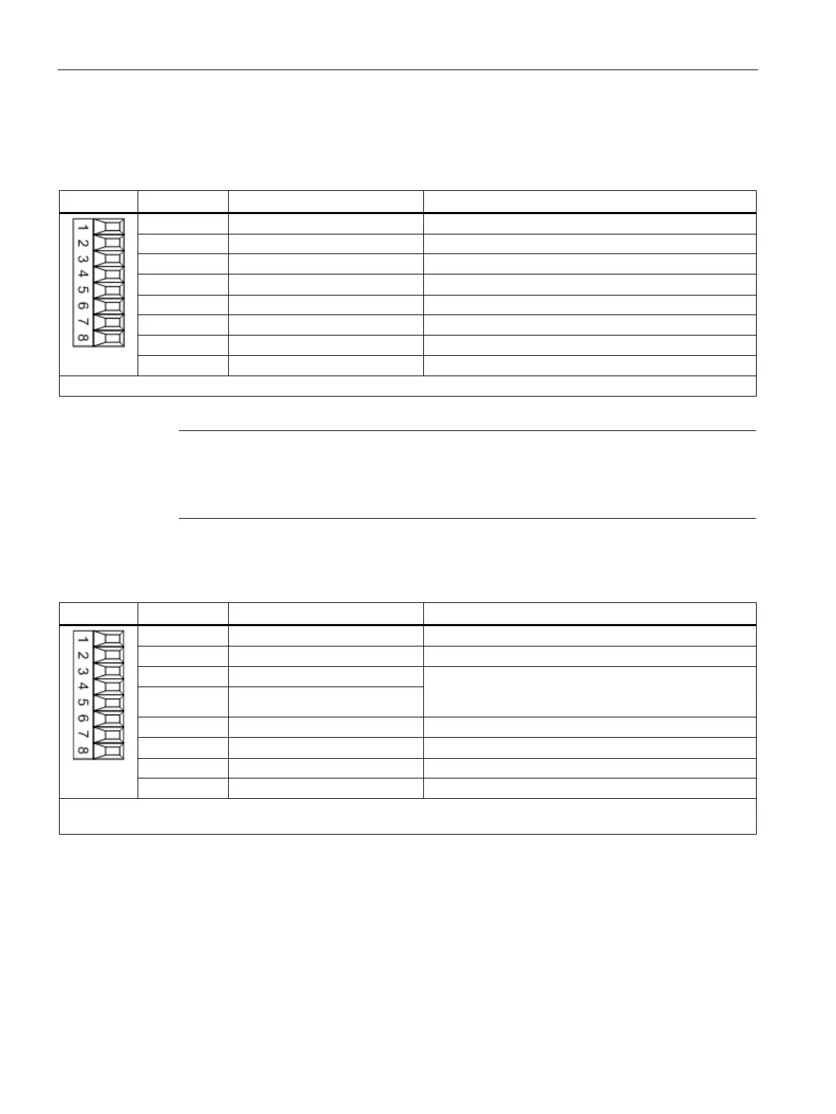
X521/X531 encoder connection 2 for HTL/TTL/SSI encoder with open-circuit monitoring
Table 8- 13 Encoder connection X521
Inverted incremental signal A
4 B* Inverted incremental signal B
Inverted reference signal R
Max. connectable cross-section #16 AWG (1.5 mm²)
Note
Operation of unipolar HTL encoders
When unipolar HTL encoders are used, terminal block A*, B*, and R* must be jumpered with
M encoder (
-X531).
Table 8- 14 Encoder connection X531
Motor temperature measurement KTY84-1C130 (KTY-)
Temperature sensor KTY84-1C130/PTC/
bimetallic switch with NC contact
4 +Temp
6 Clock* Inverted SSI clock
max. connectable cross-section #16 AWG (1.5 mm²)
When using unipolar HTL encoders, at the terminal block A*, B*, R* must be connected to (jumper) M_Encoder (X531)
1)
Because the physical transmission media is more robust, the bipolar connection should always be used. The unipolar
connection should only be used if the encoder type does not output push-pull signals.
 Loading...


