Mechanical installation
3.3 Installation
Cabinet Modules NEMA
Manual, 04/2014, A5E03586450A
49
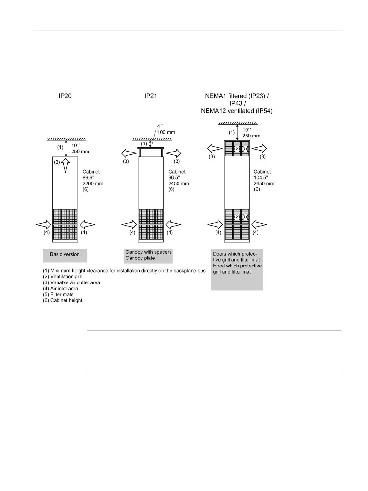
The cabinet units are installed in accordance with the dimension drawings supplied. The
clearance between the top of the cabinet and the ceiling is shown in the figure below.
Additional dimensions must be taken into account for the M06 (cabinet base) and M07 (cable
marshalling compartment) options.
Figure 3-1 Required room height for different enclosures (without options M06 and M07)
Note
Further dimensions
Additional dimensions can be found in the relevant dimension drawings on the customer
DVD supplied with the device.
The cooling air for the power unit is drawn in from the front through the ventilation grills in the
lower part of the cabinet doors. The heated air is released through the perforated top cover
or the ventilation grills in the hood (with options M23/M43/M54 for degrees of protection IP23
(NEMA1 filtered)/IP43/IP54 (NEMA12 ventilated)). Cooling air can also be supplied from
below through raised floors or air ducts, for example. To allow this, openings must be made
in the sectioned bottom plate.
 Loading...


