Electrical installation
4.5 Connections
Cabinet Modules NEMA
Manual, 04/2014, A5E03586450A
77
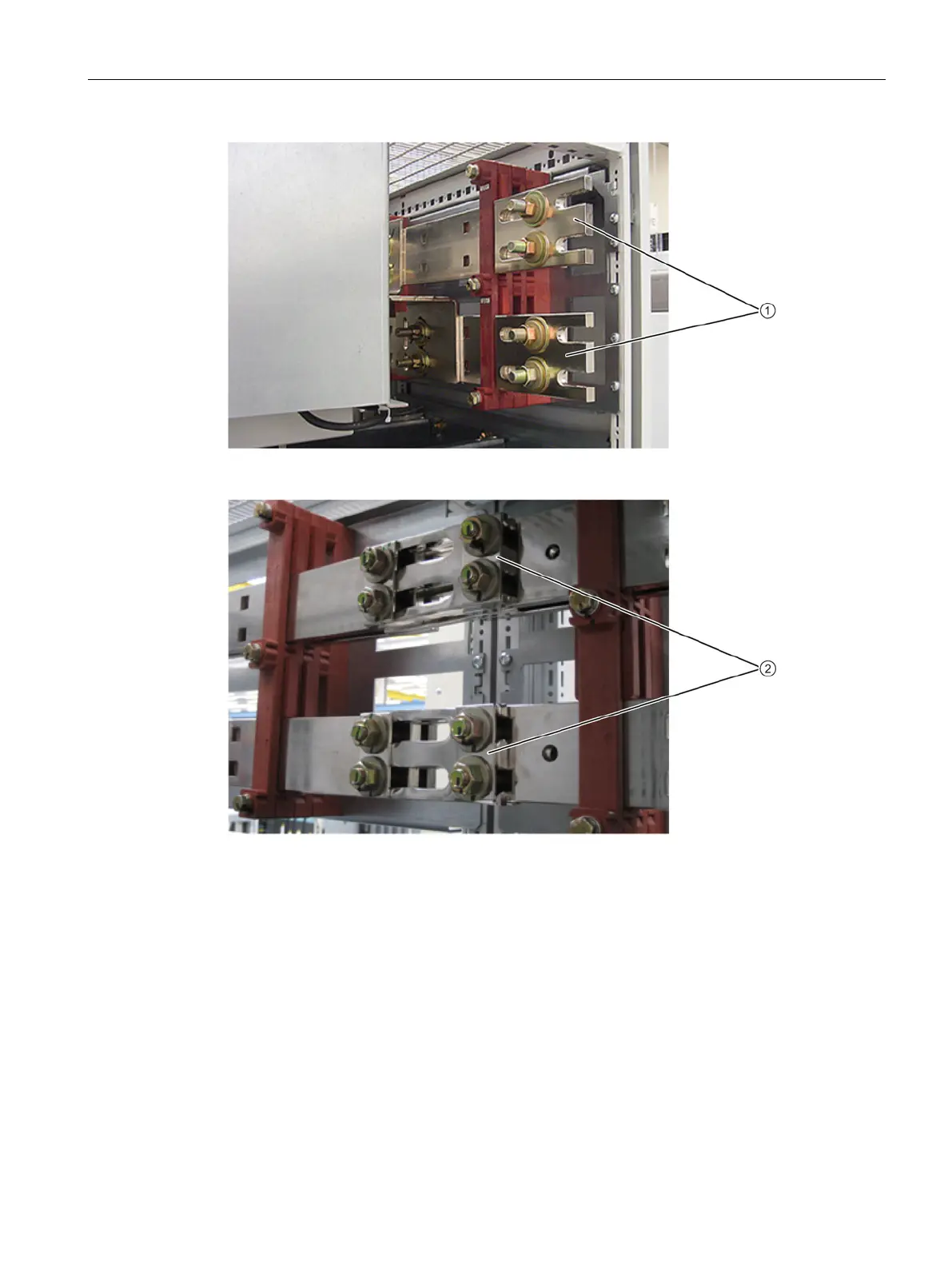
Figure 4-4 Factory state of the DC busbar
Figure 4-5 Connecting the DC busbar when cabinet units are installed side-by-side
Establishing the connection
1. Loosen the 2 x M12 nuts on the upper DC busbar (DC P) on the right side ① at the first
cabinet.
2. Loosen the 2 x M12 nuts on the DC busbar on the left side of the cabinet to be
connected.
3. Pull jumper
① of the DC busbar from the first cabinet and plug it into the DC busbar of
the second cabinet up to its end stop
②.
 Loading...


