STOBER 8 | Connection
12/2018 | ID 442537.05
107
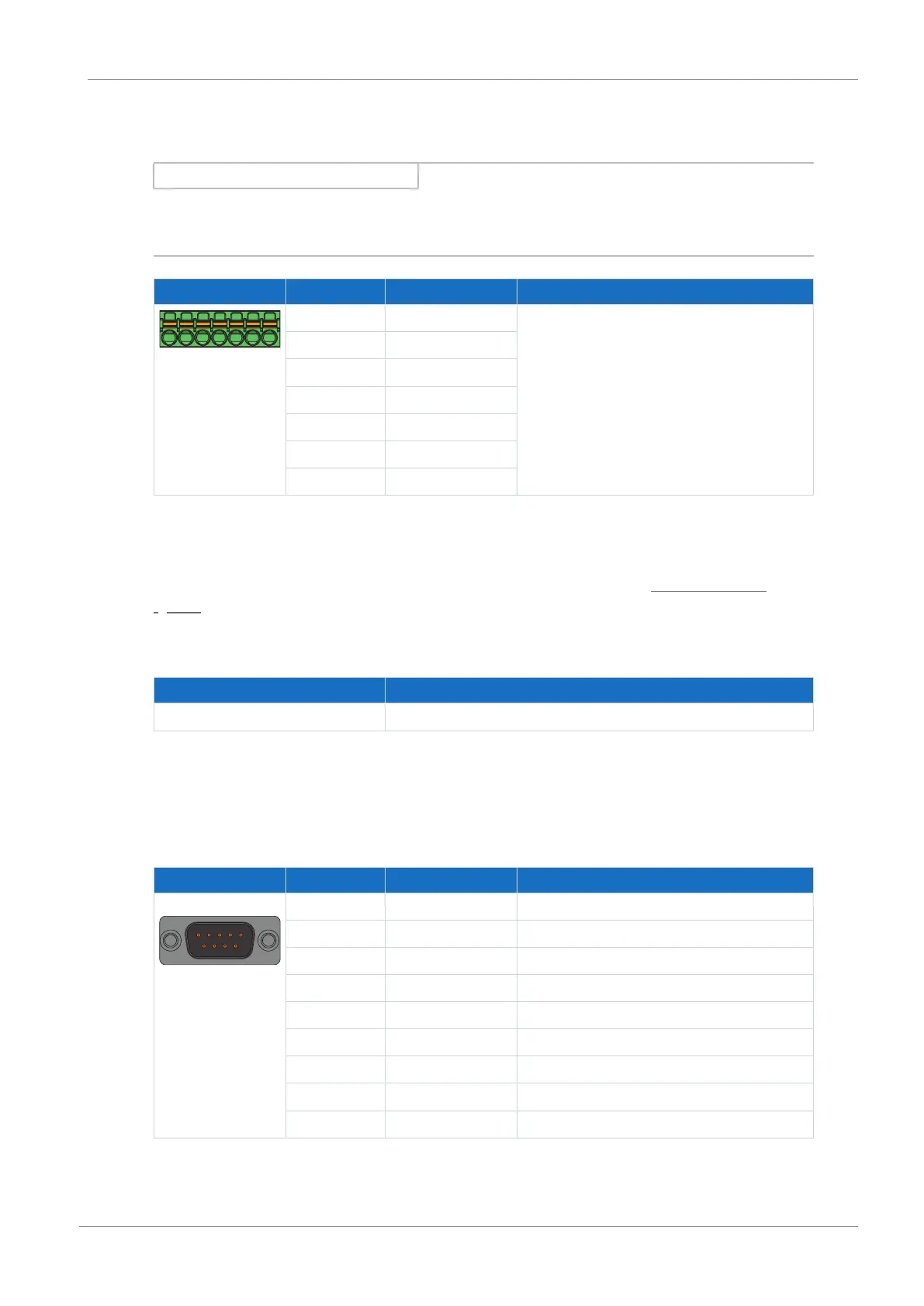
8.6.1.7 X103C: BE7 – BE13
Information
In the event of failure of the 24V
DC
supply, the binary inputs BE7 to BE13 display the signal
state 0, regardless of the physical signal state.
Terminal Pin Designation Function
10|11| ... |15|16
10 BE7 Binary input
11 BE8
12 BE9
13 BE10
14 BE11
15 BE12
16 BE13
Tab. 112: X103C connection description
Connecting wiring
For connecting wiring, observe the terminal specifications in the chapter FMC 1,5 -ST-3,5
[}151].
Cable requirements
Feature All sizes
Max. cable length 30m
Tab. 113: Cable length [m]
8.6.1.8 X120
SSI encoders
Connector Pin Designation Function
1 | 2 | 3 | 4 | 5
6 | 7 | 8 | 9
1 GND-ENC Reference potential for pin4 to pin7
2 — —
3 — —
4 Clock− Inverse differential input/output for CLOCK
5 Clock+ Differential input/output for CLOCK
6 Data+ Differential input/output for DATA
7 Data− Inverse differential input/output for DATA
8 U
2
Encoder supply
9 GND Reference potential for pin 8
Tab. 114: X120 connection description for SSI encoders

 Loading...

