8 | Connection STOBER
106
12/2018 | ID 442537.05
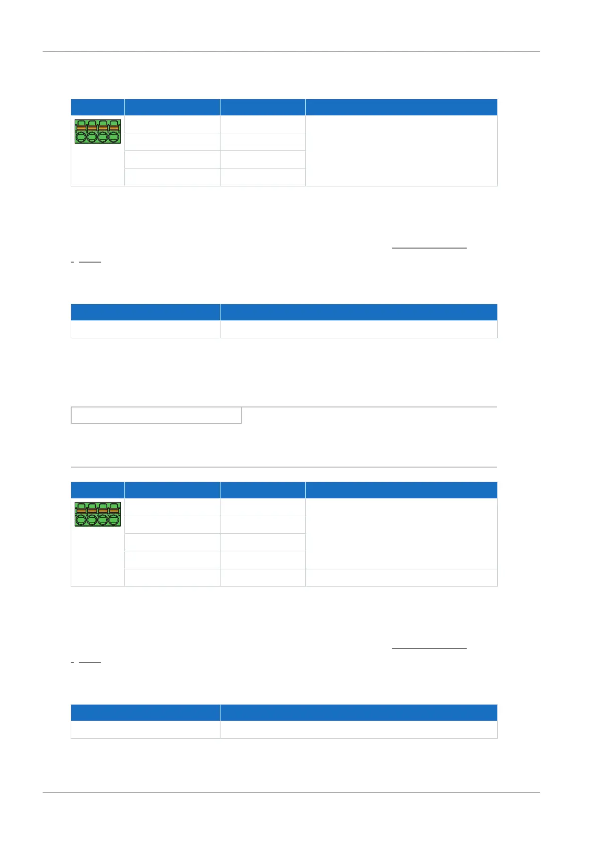
8.6.1.5 X103A: BA3 – BA6
Terminal Pin Designation Function
1|2|3|4
1 BA3 Binary outputs
2 BA4
3 BA5
4 BA6
Tab. 108: X103A connection description
Connecting wiring
For connecting wiring, observe the terminal specifications in the chapter FMC 1,5 -ST-3,5
[}151].
Cable requirements
Feature All sizes
Max. cable length 30m
Tab. 109: Cable length [m]
8.6.1.6 X103B: BE6, BA7 – BA10
Information
In the event of failure of the 24V
DC
supply, the binary input BE6 displays the signal state 0,
regardless of the physical signal state.
Terminal Pin Designation Function
5|6|7|8|9
5 BA7 Binary output
6 BA8
7 BA9
8 BA10
9 BE6 Binary input
Tab. 110: X103B connection description
Connecting wiring
For connecting wiring, observe the terminal specifications in the chapter FMC 1,5 -ST-3,5
[}151].
Cable requirements
Feature All sizes
Max. cable length 30m
Tab. 111: Cable length [m]

 Loading...

