STOBER 8 | Connection
12/2018 | ID 442537.05
113
8.6.2.4 X120
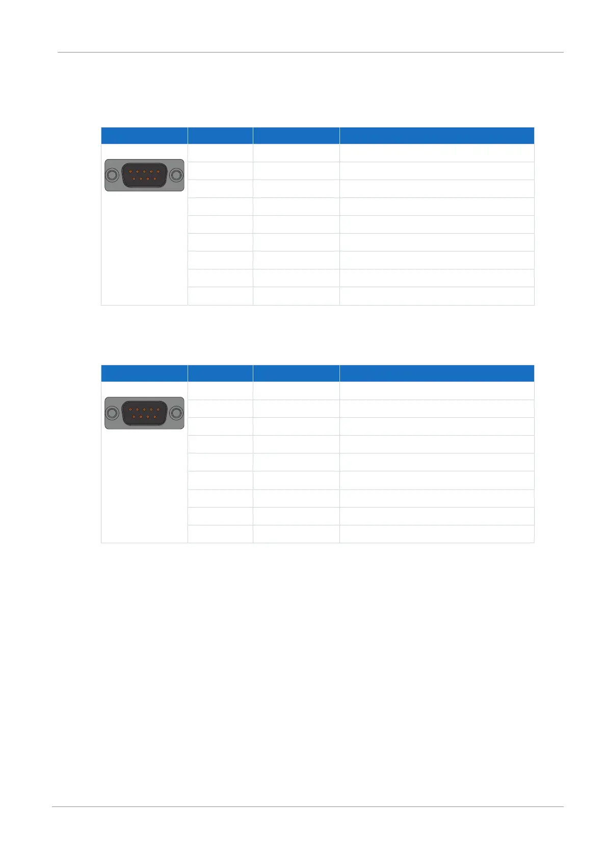
SSI encoders
Connector Pin Designation Function
1 | 2 | 3 | 4 | 5
6 | 7 | 8 | 9
1 GND-ENC Reference potential for pin4 to pin7
2 — —
3 — —
4 Clock− Inverse differential input/output for CLOCK
5 Clock+ Differential input/output for CLOCK
6 Data+ Differential input/output for DATA
7 Data− Inverse differential input/output for DATA
8 U
2
Encoder supply
9 GND Reference potential for pin 8
Tab. 126: X120 connection description for SSI encoders
Differential TTL incremental encoders
Connector Pin Designation Function
1 | 2 | 3 | 4 | 5
6 | 7 | 8 | 9
1 GND-ENC Reference potential for pin4 to pin7
2 N+ Differential input/output for N channel
3 N− Inverse differential input/output for N channel
4 A− Inverse differential input/output for A channel
5 A+ Differential input/output for A channel
6 B+ Differential input/output for B channel
7 B− Inverse differential input/output for B channel
8 U
2
Encoder supply
9 GND Reference potential for pin 8
Tab. 127: X120 connection description for differential TTL incremental encoders

 Loading...

