8 | Connection STOBER
114
12/2018 | ID 442537.05
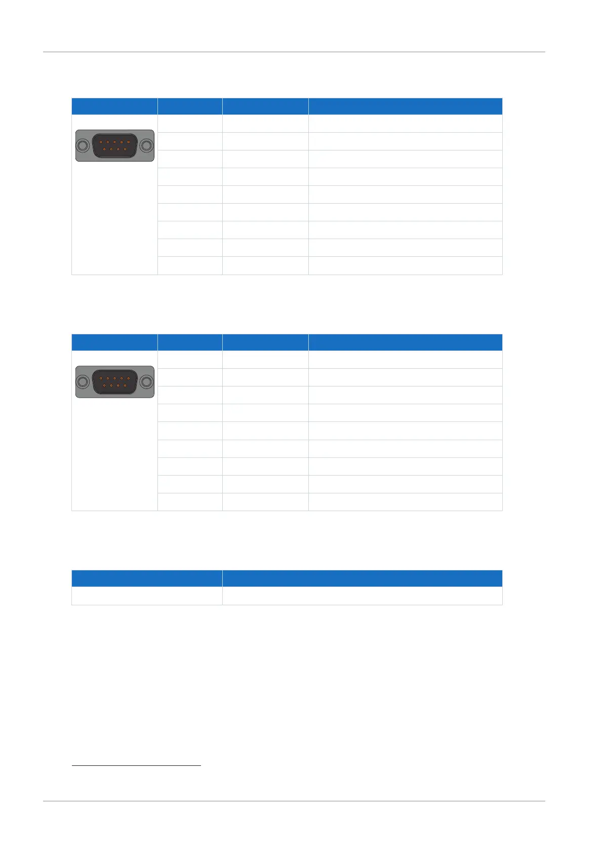
Differential TTL hall sensor
Connector Pin
20
Designation Function
1 | 2 | 3 | 4 | 5
6 | 7 | 8 | 9
1 GND-HALL Reference potential for pin4 to pin7
2 HALL C+ Differential input for HALL C
3 HALL C− Inverse differential input for HALL C
4 HALL A− Inverse differential input for HALL A
5 HALL A+ Differential input for HALL A
6 HALL B+ Differential input for HALL B
7 HALL B− Inverse differential input for HALL B
8 U
2
Encoder supply
9 GND Reference potential for pin 8
Tab. 128: X120 connection description for differential TTL hall sensors
Differential TTL pulse train
Connector Pin
21
Designation Function
1 | 2 | 3 | 4 | 5
6 | 7 | 8 | 9
1 GND-ENC Reference potential for pin2 to pin7
2 — —
3 — —
4 Pulse− Inverse differential input for pulses
5 Pulse+ Differential input for pulses
6 Direction+ Differential input for direction
7 Direction− Inverse differential input for direction
8 U
2
Encoder supply
9 GND Reference potential for pin 8
Tab. 129: X120 connection description for differential TTL pulse train signals
Cable requirements
Feature All sizes
Max. cable length 50m, shielded
Tab. 130: Cable length [m]
20
1:1 connection to LA6: Pin assignment corresponds to terminal X301
21
1:1 connection to LA6: Pin assignment corresponds to terminal X301

 Loading...

