STOBER 8 | Connection
12/2018 | ID 442537.05
115
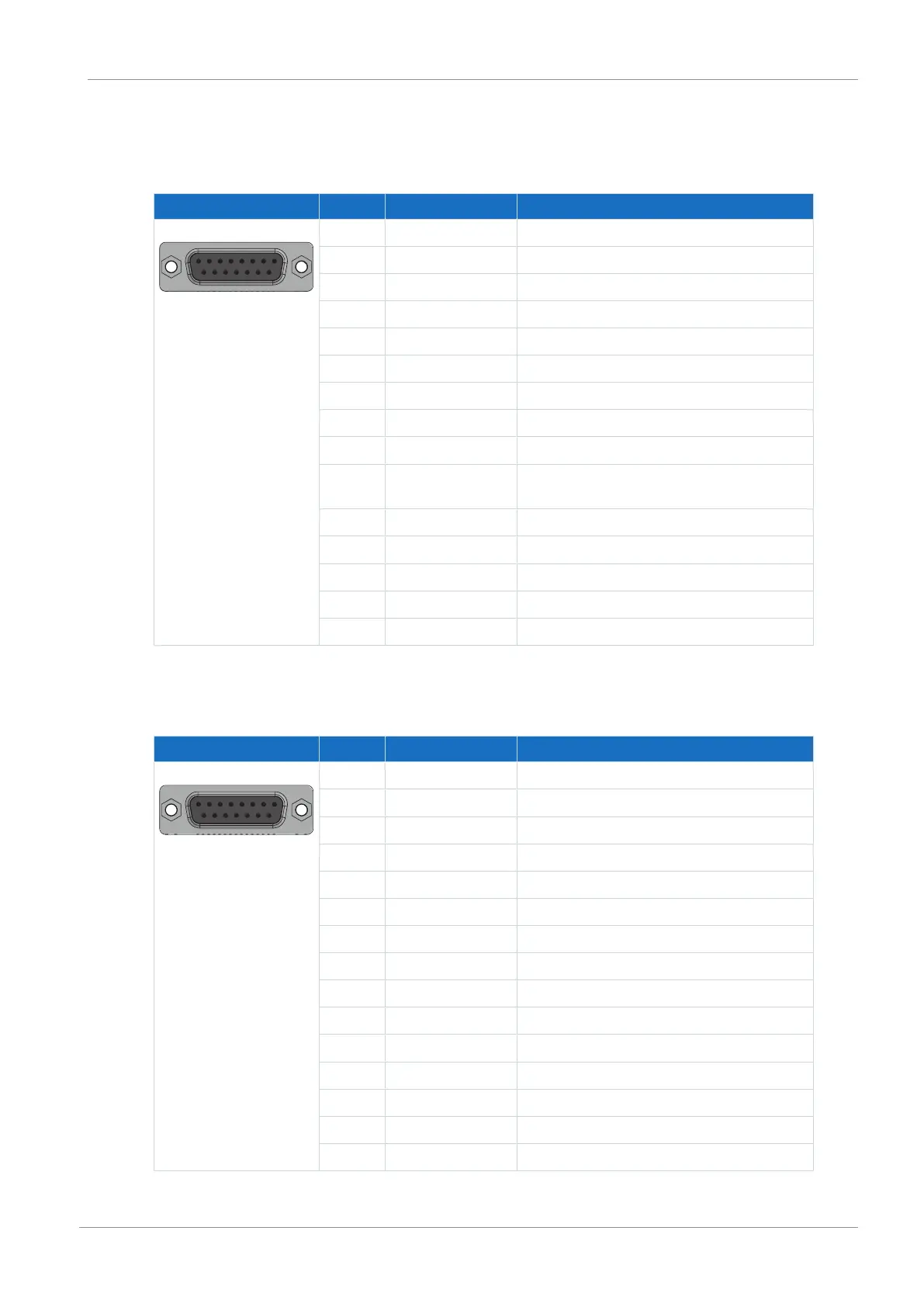
8.6.2.5 X140
EnDat 2.1/2.2 digital encoders
Socket Pin Designation Function
8|7|6|5|4|3|2|1
15|14|13|12|11|10|9
1 — —
2 GND Reference for encoder supply at pin 4
3 — —
4 U
2
Encoder supply
5 Data+ Differential input for DATA
6 — —
7 — —
8 Clock+ Differential input for CLOCK
9 — —
10 Sense GND Optional sensing lead for the supply voltage
for regulating the encoder supply
11 — —
12 Sense U
2
Sense signals for voltage regulation
13 Data− Inverse differential input for DATA
14 — —
15 Clock− Inverse differential input for CLOCK
Tab. 131: X140 connection description for EnDat 2.1/2.2 digital encoders
Resolver
Socket Pin Designation Function
8|7|6|5|4|3|2|1
15|14|13|12|11|10|9
1 S4 Sin+ Sin input
2 R1 Ref− Reference potential for pin 6
3 S3 Cos+ Cos input
4 — —
5 — —
6 R2 Ref+ Resolver excitation signal
7 1TP1 Reserve
8 — —
9 S2 Sin− Reference potential for pin 1
10 — —
11 S1 Cos− Reference potential for pin 3
12 — —
13 — —
14 1TP2 Reserve
15 — —
Tab. 132: X140 connection description for resolvers

 Loading...

