STOBER 8 | Connection
12/2018 | ID 442537.05
117
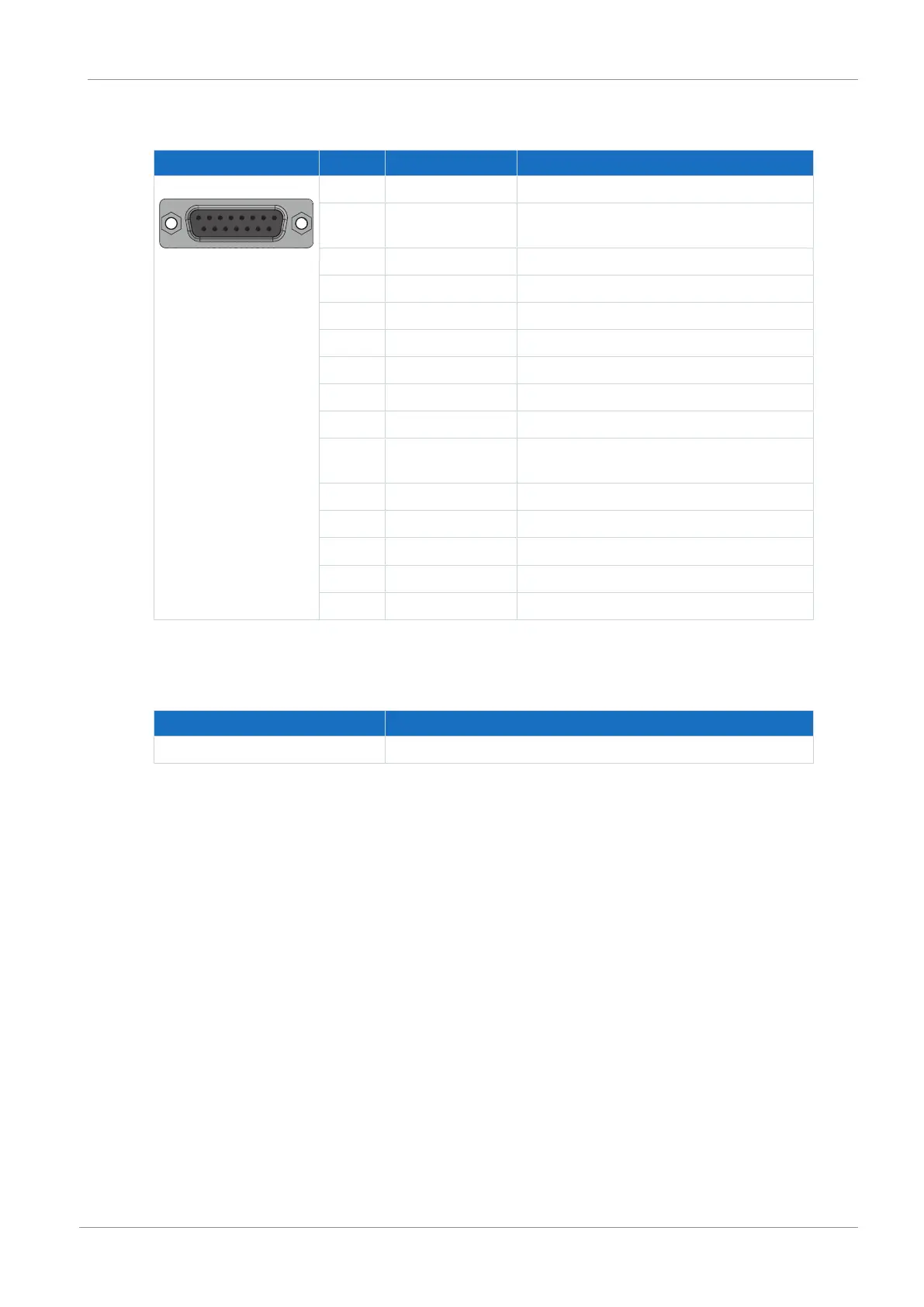
Sin/cos encoders
Socket Pin Designation Function
8|7|6|5|4|3|2|1
15|14|13|12|11|10|9
1 B− (Sin−) Reference potential for sin input
2 GND Reference potential for encoder supply to pin
4
3 A− (Cos−) Reference potential for cos input
4 U
2
Encoder supply
5 — —
6 — —
7 — —
8 — —
9 B+ (Sin+) Sin input
10 Sense GND Optional sensing lead for the supply voltage
for regulating the encoder supply
11 A+ (Cos+) Cos input
12 Sense U
2
Sense signals for voltage regulation
13 — —
14 — —
15 — —
Tab. 134: X140 connection description for sin/cos encoders
Cable requirements
Feature All sizes
Max. cable length 100m, shielded
Tab. 135: Cable length [m]

 Loading...

