8 | Connection STOBER
118
12/2018 | ID 442537.05
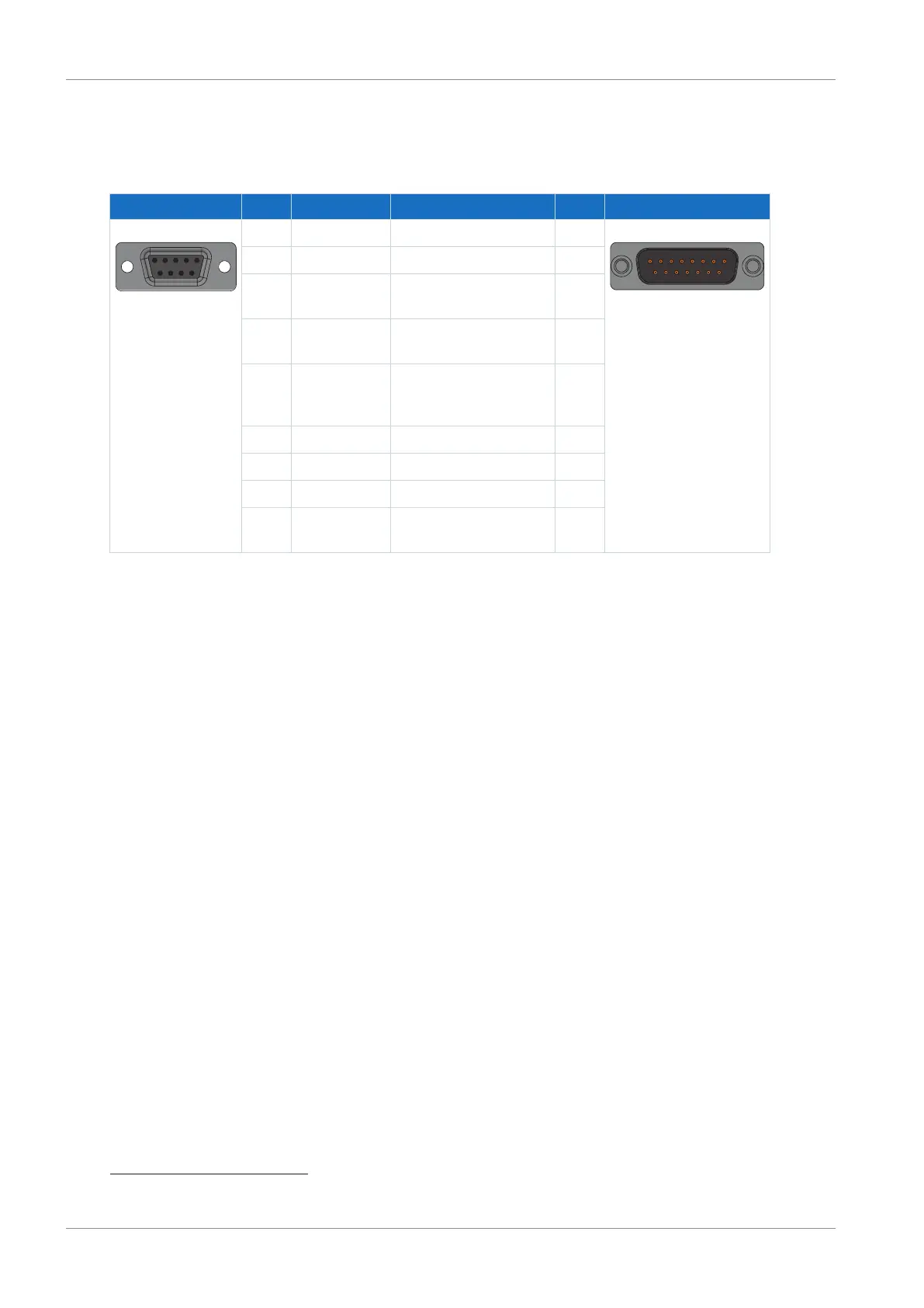
8.6.2.6 AP6 interface adapter (resolver)
AP6A00 – Resolver (9-pin to 15-pin)
Socket
22
Pin Designation Function Pin Connector
23
1 | 2 | 3 | 4 | 5
6 | 7 | 8 | 9
1 — — — 1|2|3|4|5|6|7|8|9
10|11|12|13|14|15
2 1TP1 — —
3 S2 Sin− Sin input reference
potential
9
4 S1 Cos− Cos input reference
potential
11
5 R1 Ref− Resolver excitation
signal reference
potential
2
6 1TP2 — —
7 S4 Sin+ Sin input 1
8 S3 Cos+ Cos input 3
9 R2 Ref+ Resolver excitation
signal
6
Tab. 136: Connection description of AP6A00 for resolver (9-pin to 15-pin)
22
View of 9-pin D-sub for connecting the SDS 4000-compatible resolver cable
23
View of 15-pin D-sub for connecting to SD6, terminal X140 (RI6)

 Loading...

