STOBER 7 | Installation
12/2018 | ID 442537.05
43
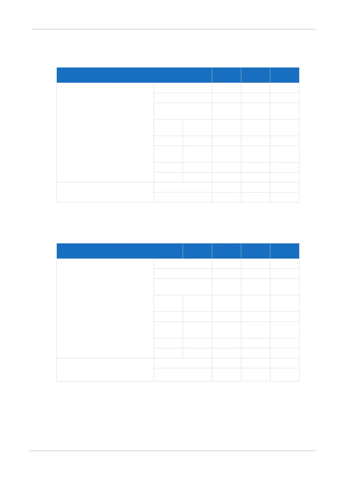
The bore dimensions depend on the selected design.
The following specifications apply to installation without a rear section module:
SD6 dimension Size0,
size1
Size2 Size3
Horizontal SD6 fastening holes
∅4.2 (M5)
A 70 105 —
B — — 20
E — — 150+0.2/
−0.2
C Size0,
size1
76±1 93.5±1 —
C Size2 93.5±1 111±1 —
D Size0,
size1
— — 61±1
D Size2 — — 78.5±1
D Size3 — — 46±1
Vertical SD6 fastening holes
∅4.2 (M5)
F 283+2 283+2 —
G — — 365+2
Tab. 45: Bore dimensions for SD6 drive controller [mm]
The following specifications apply to installation with a DL6A Quick DC-Link or rear section
braking resistor:
DL6A dimension / rear section braking resistor Size0,
size1
Size2 Size3
Horizontal fastening holes for rear
section modules
∅4.2 (M5)
A 70 105 —
B — — 20
E — — 150+0.2/
−0.2
C Size0,
size1
74+1 91.5+1 —
C Size2 91.5+1 109+1 —
D Size0,
size1
— — 63+1
D Size2 — — 80.5+1
D Size3 — — 52+1
Vertical fastening holes for rear section
modules
∅4.2 (M5)
F 283+2 283+2 —
H — — 380+2
Tab. 46: Bore dimensions for DL6A Quick DC-Link or rear section braking resistor [mm]
 Loading...


