7 | Installation STOBER
54
12/2018 | ID 442537.05
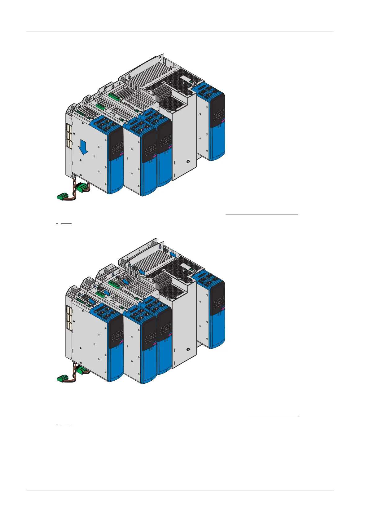
3. Press the drive controller downward onto the guides.
4. Sizes 0 to 2: Mount the EM6A0 EMC shroud; see the chapter Attaching the EMC shroud
[}58].
5. Attach the drive controller to the threaded bolts using the screw and washer assemblies.
6. Connect the grounding conductor of the rear section module to the ground bolt of the rear
section module and the grounding conductor of the drive controller to the ground bolt of the
drive controller. Note the instructions and requirements in the chapter Housing grounding
[}65].

 Loading...

