ELECTRICAL SYSTEM 13-5
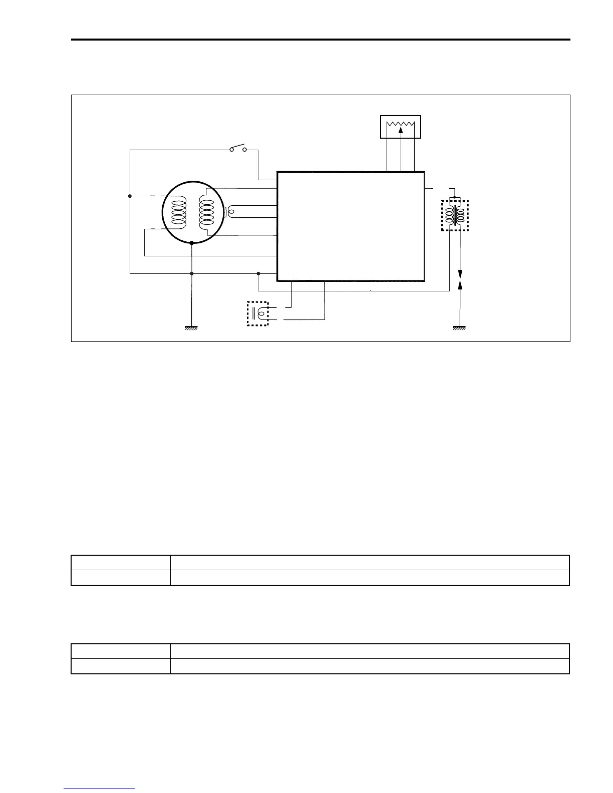
ELECTRICAL CIRCUIT
COLOR CODE
B: Black B/R: Black with Red tracer
G: Green B/W: Black with White tracer
R: Red B/Y: Black with Yellow tracer
Y: Yellow Bl/B: Blue with Black tracer
B/Bl: Black with Blue tracer R/W: Red with White tracer
B/Br: Black with Brown tracer W/Bl: White with Blue tracer
B/G: Black with Green tracer
TROUBLESHOOTING (No spark or poor spark)
Step 1
1) Check the ignition system couplers for poor connections.
Is there connection in the ignition system couplers?
Step 2
1) Measure the peak voltage of ignition coil. (13-7)
Is the peak voltage OK?
YES Go to Step 2.
NO Poor connection of couplers
YES Go to Step 3.
NO Go to Step 4.
Magneto
Engine stop switch
CDI unit
Throttle position sensor
Ignition coil
Spark plug
Carburetor
solenoid
B/R
B/W
R
G
B
B/R
R/W
R
G
B
Bl/BBl/B
B/G
B/WB/W
B/WB/W
YYYY
B/YB/Y
B/Br
B/Bl
B/Br
B/G
B/Bl
B/W
B/W
W/Bl
W/Bl
W/Bl