High linear operating range for the sinusoidal signal.
The calibration factor is always added to the upper range
limit.
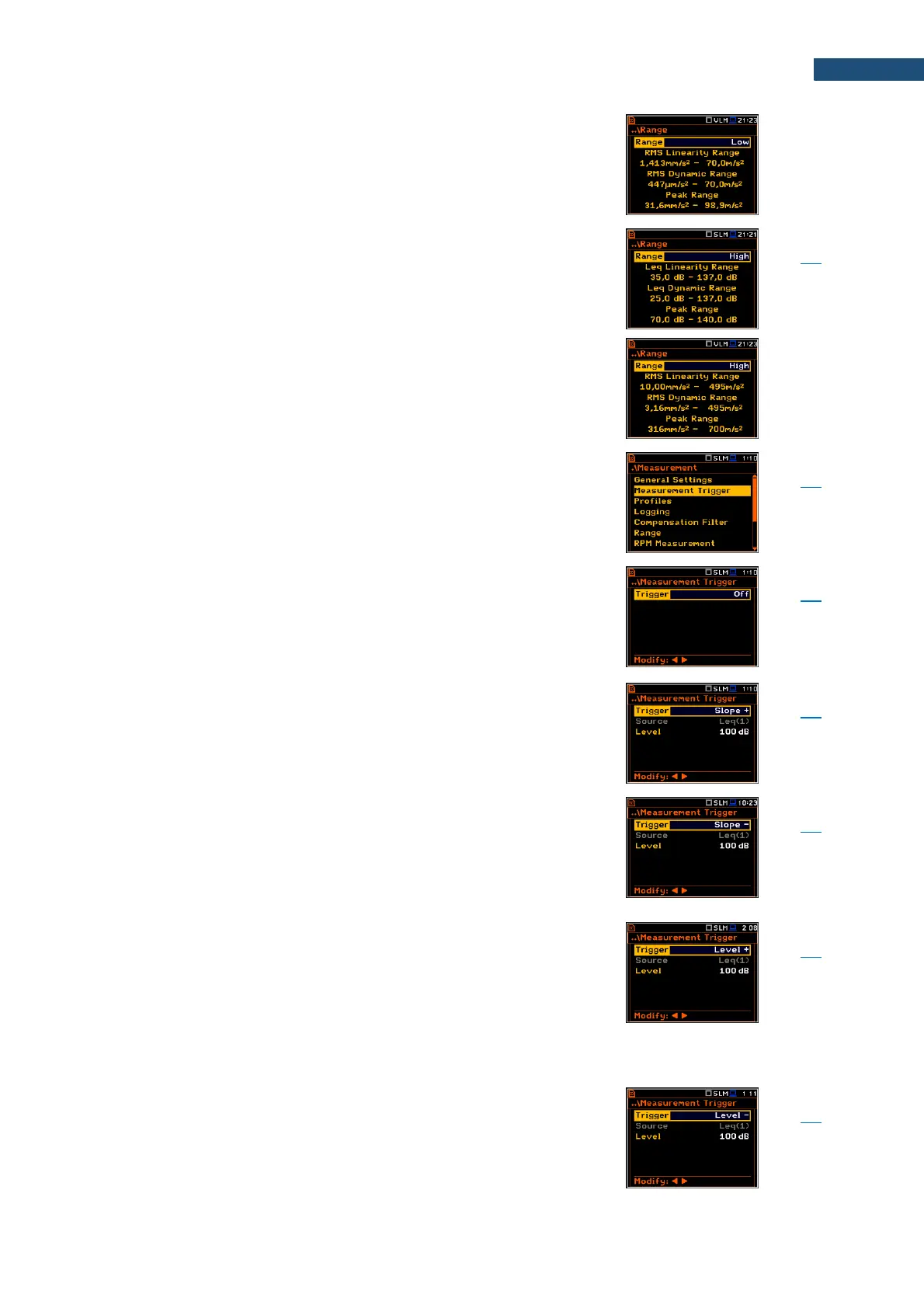
The range depends on the selected Compensation Filter.
Screen that enables configuring trigger of the
measurement/integration process with parameters:
Trigger, Source, Level and Gradient.
Position that switches Off or on the measurement trigger
by selecting its type: Slope +, Slope –, Level +, Level –,
Grad + or External.
If the instrument is waiting for the trigger condition, the
appropriate trigger icon is flashing on the display
alternatively with the „measurement” icon.
Type of trigger that starts the measurement/integration
by the duration of the Integration Period under the
condition: rising value of the RMS result (Source)
integrated during 0,5 ms passes above the threshold
level (Level).
Type of trigger that starts the measurement/integration
by the duration of the Integration Period under the
condition: falling value of the RMS result (Source)
integrated during 0,5 ms passes below the threshold
level (Level).
Type of trigger that starts the 1-second measurement/
integration under the condition: value of the RMS result
(Source) integrated during 0,5 ms is greater than the
threshold value (Level). In other cases, the instrument
continues checking the trigger condition every 0,5 mc.
During one measurement cycle the instrument performs
as many 1-second integrations as many seconds the
Integration Period consists and stops the measurement
cycle.
Type of trigger that starts the 1-second measurement/
integration under the condition: value of the RMS result
(Source) integrated during 0,5 ms is lower than the
threshold value (Level). In other cases, the instrument
continues checking the trigger condition every 0,5 mc.
During one measurement cycle the instrument performs
as many 1-second integrations as many seconds the