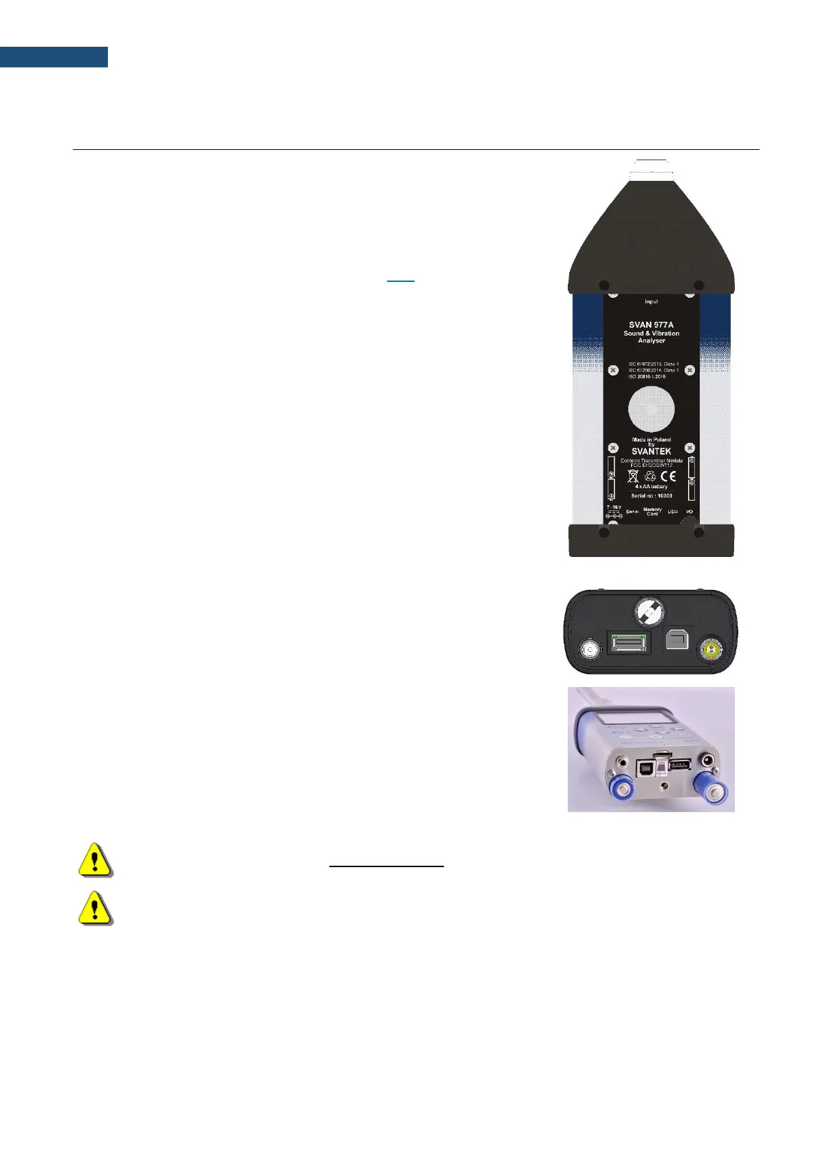
Top cover of the instrument
The measurement input is placed in the centre of the instrument’s top cover.
It is the TNC compatible socket. The SV 12L microphone preamplifier has a
specially designed matching TNC plug and a locking screw to secure the
preamplifier to the meter body. The accelerometers must be connected to
the instrument also using the TNC connector. The microphone and
accelerometer attaching are described in Chapter 14.3. The full description
of the signals connected to the socket is given in Appendix C.
Bottom cover of the instrument
In the bottom cover, there are four sockets, placed from the right to the left
as follows: 7-16V, Serial, USB and I/O.
There is a memory micro SD-card socket (Memory Card) under the bottom
cover of the instrument and spaces for the 4 x AA batteries.
The USB socket is the USB Device 1.1 interface – a serial interface working
with 12 MHz clock. Thanks to its speed, it is widely used in all PCs. In the
instrument, the standard 4-pin socket is used.
The Serial socket is the Serial Port with RS232 data transfer format in TTL
logic standard by means of the SV 55 interface. It conforms to the EIA
Standard RS 232C and enables remote programming of all instrument
functions and transmission to and from the instrument with speed from 300
bit/s to 115200 bit/s.
The additional multi-purpose input/output socket, called I/O, is a 3.5 mm jack
socket. In case the Analogue Output functionality is selected, the signal from
the input of the analogue/digital converter (before any frequency correction)
is available on this socket. This signal can be recorded using a magnetic
recorder or observed on an oscilloscope. The Digital Input as another
functionality that serves as the external trigger to the instrument, while the
Digital Output is used to generate the trigger pulse or alarm pulse from the
instrument.
You can connect an external DC power 7-16V adapter to the 7-16V socket
located on the bottom cover of the instrument. The current consumption
depends on the voltage of the power supplier.
There is a micro SD-card memory slot under the bottom cover of the
instrument and spaces for the 4 x AA batteries.
All sockets are described in detail in Appendix C for this manual.