EasyManua.ls Logo

Svantek SVAN 977A - Page 201

Svantek SVAN 977A
302 pages
Print Icon
To Next Page IconTo Next Page
To Previous Page IconTo Previous Page
Loading...
201
SVAN 977A User Manual - Appendixes
Note: For the conformance tests with B&K4226 multifrequency calibrator, the Microphone
Compensation must be set to “On! (path: <Menu> / Measurement / Compensation Filter).
Note: For the conformance of acoustical tests, the Microphone Compensation must be set to
Free Field and the Windscreen position must be set to “Off”! (path: <Menu> / Measurement /
Compensation Filter).
If the case of Windscreen testing the Windscreen position must be set to “On”.
Periodical test upper frequency 8 kHz
Linear Operating Ranges
Two measuring ranges are available: “LOW” and "HIGH".
The starting point at which tests of level linearity shall begin is 94.0 dB for the frequencies specifies below.
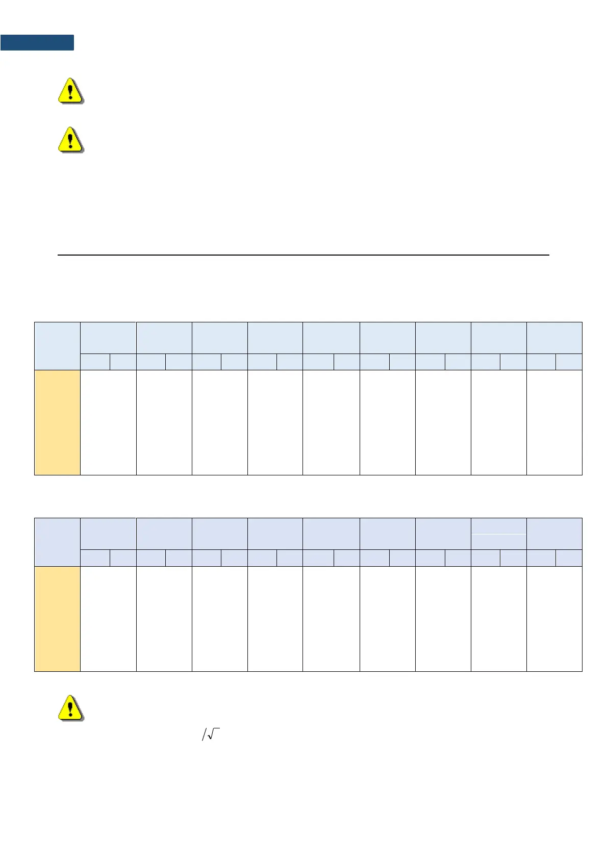
Table C.1.1. Linear operating range: “LOWfor the sinusoidal signal and microphone sensitivity 35 mV/Pa
[dB]
L
AS/F
L
BS/F
L
CS/F
L
ZS/F
L
AeqT
L
BeqT
L
CeqT
L
AE
L
Cpeak
(t
int
= 2 s)
from
to
from
to
from
to
from
to
from
to
from
to
from
to
from
to
from
to
31,5 Hz
25
80
25
103
25
117
30
120
25
80
25
103
25
117
28
83
50
120
500 Hz
25
116
25
119
25
120
30
120
25
116
25
119
25
120
28
119
50
123
1 kHz
25
120
25
120
25
120
30
120
25
120
25
120
25
120
28
123
50
123
4 kHz
25
121
25
119
25
119
30
120
25
121
25
119
25
119
28
124
50
123
8 kHz
25
119
25
117
25
117
30
120
25
119
25
117
25
117
28
122
50
120
12.5
kHz
25
115
25
114
25
114
30
120
25
115
25
114
25
114
28
118
50
117
Table C.1.2. Linear operating range: „HIGH“ (primary level range) for the sinusoidal signal and
microphone sensitivity 35 mV/Pa
[dB]
L
AS/F
L
BS/F
L
CS/F
L
ZS/F
L
AeqT
L
BeqT
L
CeqT
L
AE
L
Cpeak
(t
int
= 2 s)
from
to
from
to
from
to
from
to
from
to
from
to
from
to
from
to
from
to
31,5 Hz
35
97
35
120
35
134
40
137
35
97
35
120
35
134
38
100
60
137
500 Hz
35
133
35
136
35
137
40
137
35
133
35
136
35
137
38
136
60
140
1 kHz
35
137
35
137
35
137
40
137
35
137
35
137
35
137
38
140
60
140
4 kHz
35
138
35
136
35
136
40
137
35
138
35
136
35
136
38
141
60
139
8 kHz
35
136
35
134
35
134
40
137
35
136
35
134
35
134
38
139
60
137
12.5
kHz
35
132
35
131
35
131
40
137
35
132
35
131
35
131
38
135
60
134
Note: For the signals with the crest factor n > 1.41 upper measuring range of the RMS (LEQ and
SPL) is reduced. The valid upper limit can be calculated according to the below given formula:
, where A is the upper limit for the sinusoidal signal
Example: For the crest factor n = 10 the upper limit is A
10
= 120 dB
( )
2log20137 nA
n
=

Table of Contents

Related product manuals