*depending on instrument set-up
The user may set-up the I/O mode in the screen <Menu> / Instrument / Multifunction I/O:
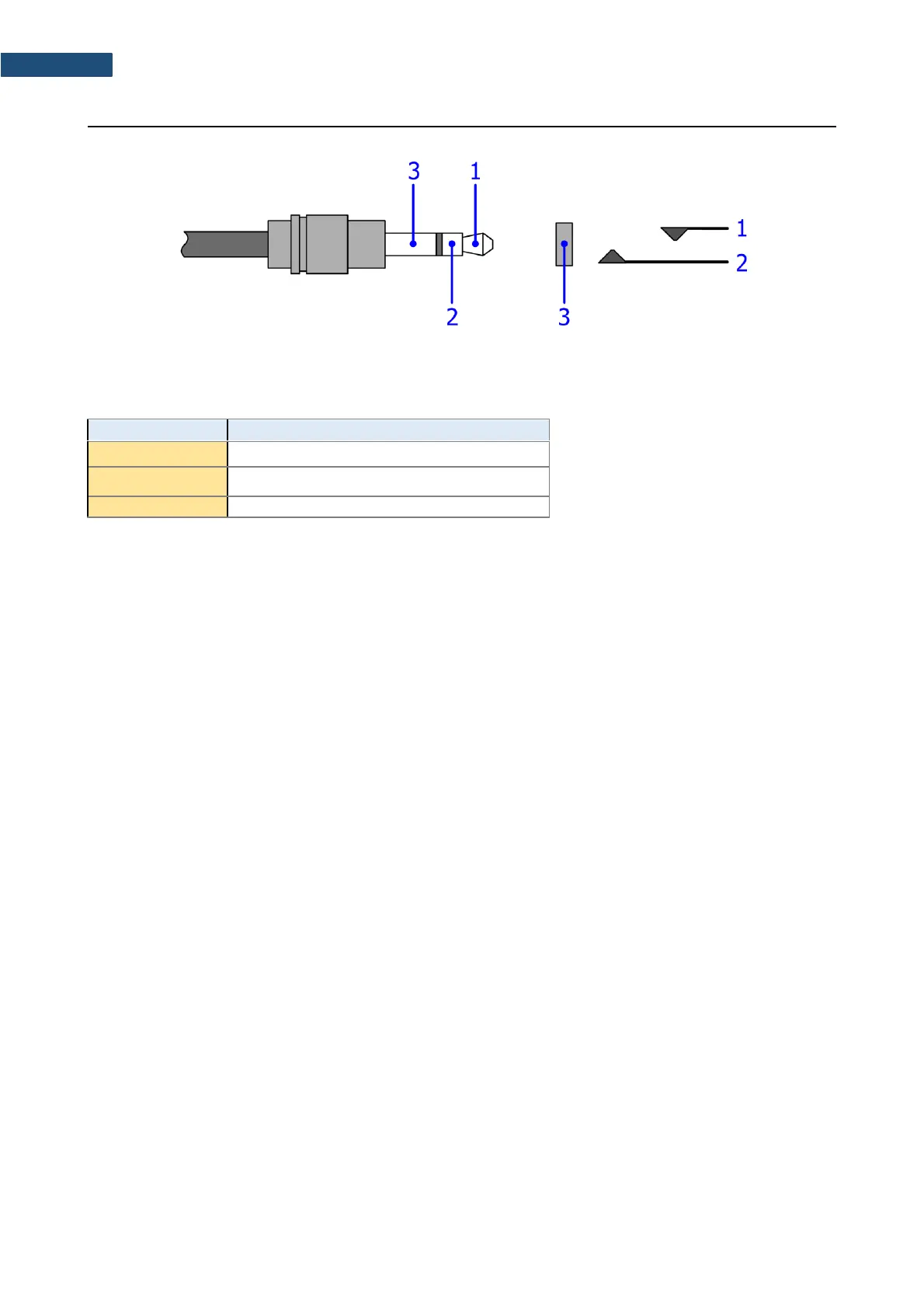
1. I/O Mode: Analog Out. When this option is selected, the measured signal from the selected channel
is fed to the terminal [1] of the I/O connector. Output voltage, frequency band and the output
impedance are following:
a) Output Voltage:
The output voltage is equal to 1.0 V
RMS
( 5 %) at:
● 120 dB indication of the instrument, on measurement range “L”
● 137 dB, indication of the instrument, on measurement range “H”,
when calibration factor is set to 0.0 dB.
b) Frequency Band (-3 dB): 0.02 Hz ÷ 40 kHz.
c) Output Impedance: 51 Ω / 5%
2. I/O Mode: Analog In – future feature.
3. I/O Mode: Digital In. When the Ext. Trigger function is activated, the external triggering of the
instrument may be provided. To do that the user should select Trigger: External (path: <Menu>
/ Measurement / Measurement Trigger). The external signal for triggering is specified as follows:
a) Trigger voltage threshold level is set to +1 V.
b) Trigger voltage slope (path: <Menu> / Measurement / Measurement Trigger) set by the user as
Slope [+] (uprising as default) or Slope [–] (falling, auxiliary).
c) Minimal duration of the trigger impulse: 10 μsec.
d) 100 μsec. release time after previous measurement is necessary before next trigger.
e) Recommended trigger voltage should not exceed ± 5 V.
f) Input impedance in the Digital In mode – ca. 10 kΩ / 100 pF, ESD type safety.
g) When the instrument is switched-off in the Digital In mode, the voltage impulse on the pin [1] will
be able to switch-on the instrument, however in this case the minimal duration of the trigger
impulse of 100 msec is necessary, with uprising voltage slope.