Technology modules
D300529 0115 - BL67 I/O modules12-36
Process output data (PZDA)
Field output data is output from an BL67-1SS
I-module to a field device.
The process output data is the data that is transfer
red by the PLC via a gateway to the BL67-1SSI-mod-
ule.
The transmission is realized in a 8-byte fo
rmat which is structured as follows:
4 bytes are used for representing the data that is to be
written to the register with the address spec-
ified at REG_WR_DATA.
1 byte contains the register address for the data
that is to be read with the next response telegram.
1 byte contains the register address of
the data to be written to bytes 0 to 3 of this telegram and a
write request.
1 byte is used for controlling the comparison operations.
1 byte contains a Stop bit for interrupting communication with
the encoder.
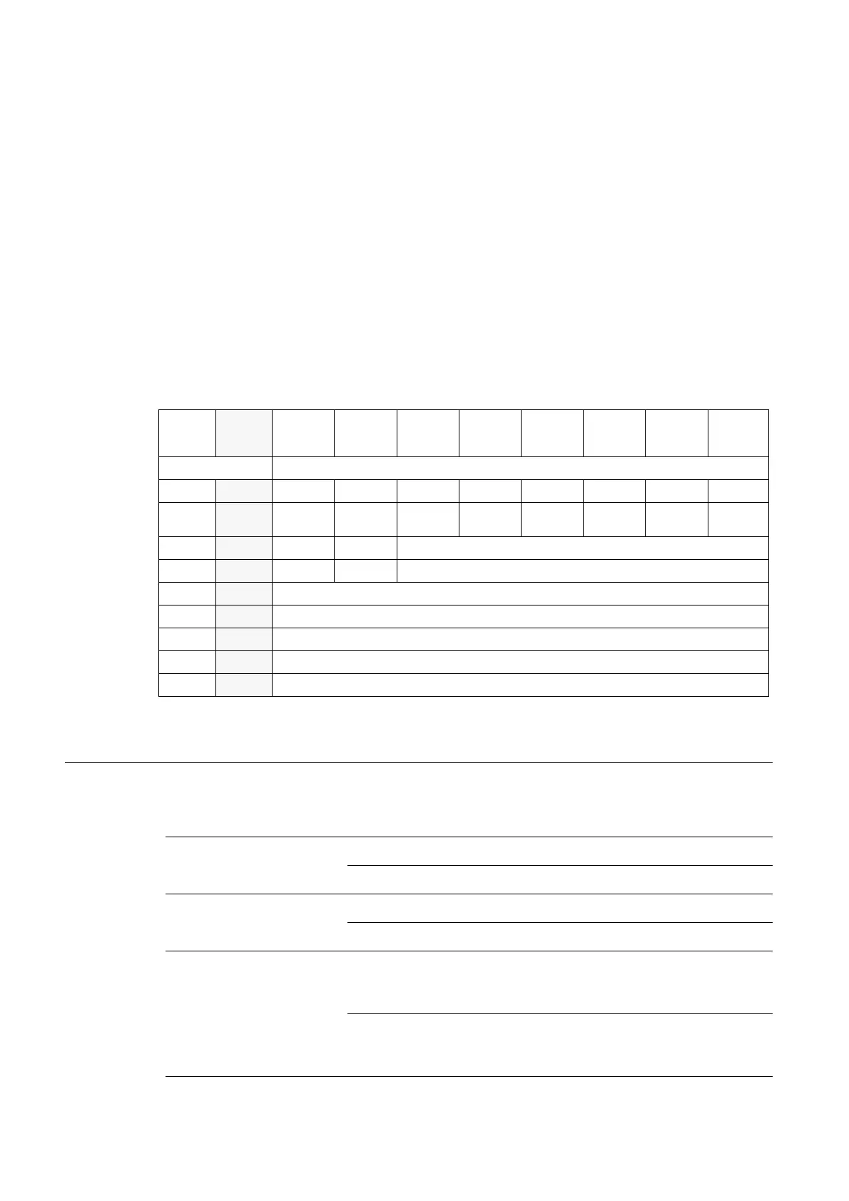
Byte Byte
DP/PN
Bit 7 Bit 6 Bit 5 Bit 4 Bit 3 Bit 2 Bit 1 Bit 0
n = offset of input data; depending on extension of station and the corresponding fieldbus.
Meaning of the data bits (process output)
Control data
n
n + 7
STOP-------
n + 1 n + 6
---
CLR
CMP2
EN
CMP2
-
CLR
CMP1
EN
CMP1
n + 2 n + 5
REG_WR - REG_WR_ADR
n + 3 n + 4
- - REG_RD_ADR
Data bytes
n + 4
n + 3
REG_WR_DATA, data byte 0
n + 5 n + 2
REG_WR_DATA, data byte 1
n + 6 n + 1
REG_WR_DATA, data byte 2
n + 7 n
REG_WR_DATA, data byte 3
Table 12-2:
Meaning of the
d
ata bits (process
output)
Designation Value Description
STOP 0 Request to read the SSI encoder cyclically
1
Request to interrupt communication with the encoder
CLR_CMP2 0 Default status, i.e. no reset of FLAG_CMP2 active.
1 Reset of FLAG_CMP2 active.
EN_CMP2 0 Default status, i.e. the data bits REL_CMP2, STS_CMP2 and
FLAG_CMP2 always have the value 0, irrespective of the
actual SSI encoder value.
1 Comparison active, i.e. the data bits REL_CMP2, STS_CMP2
and FLAG_CMP2 always have a value based on the result of
the comparison with the SSI encoder value.
 Loading...

