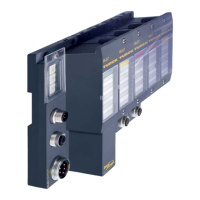
Technology modules
D300529 0115 - BL67 I/O modules12-72
In general, the following applies:
After synchronization is successfully completed the SYNC_AKN status bit is set. This bit can only be
reset by a new setting of the bit SYNC_REQ.
The signal of a bounce-free switch or the zero position of an encoder can be used as reference signal.
Behavior of the digital inputs DI0 to DI3
The digital input can be operated using different sensors (PNP-switch or push-pull-contact).
The input signal can be inverted.
The status-bits DI0 to DI3 display the level of the digital input.
The following functions can be selected for the digital inputs:
Digital input
Hardware gate (see parameter Gate function)
Encoder GND (see parameter Function DI3).
Behavior of the digital outputs DO0 to DO3
The module provides "real" digital outputs with overload detection (see Diagnostics).
The following functions can be selected for the digital outputs:
Digital output:
The digital outputs are controlled via a flag in the Process data of the module, page 12-79.
Encoder power supply (see parameter Function DO3)
Signal-evaluation options for encoders
The setting of the evaluation options is done in the BL67 counter module. The following settings are
possible:
single
double
fourfold

 Loading...