15. Raise and latch the Top Cover.
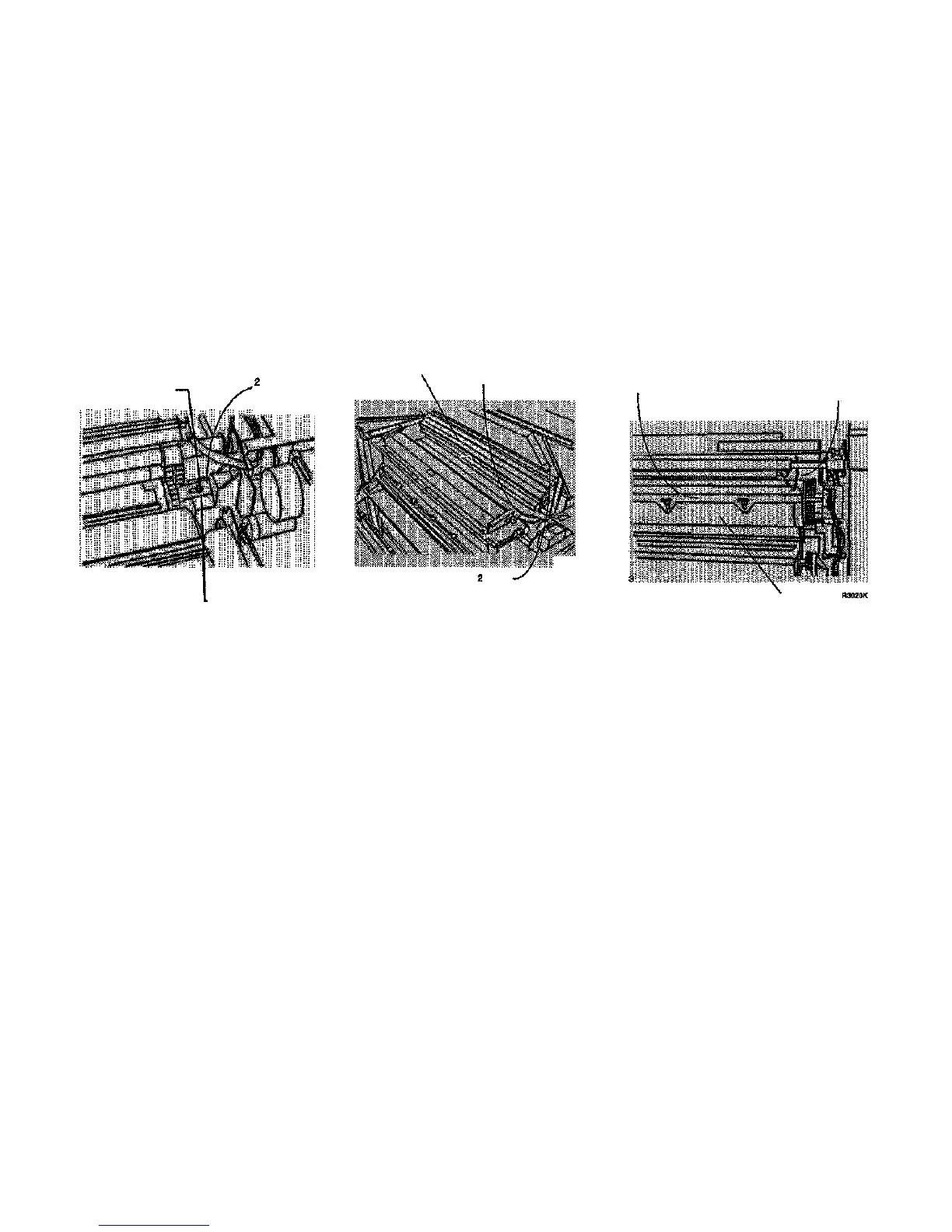
16. (Figure 2): Raise the Image Module to
engage the Developer Module shipping
brackets.
17. (Figure 3): Install the shipping pads.
1
Loosen screw Slide bracket
onto the shaft
R3016K
4
Repeat steps 1 through
3 on other side
Figure 2. Engaging the Shipping Brackets
Image Module at
Service Position
1
install the shipping
pads, one on each
end of photoreceptor
R3016K
Install the foam pads,
one on each side
Figure 3. Installing the Shipping Pads
18. Remove the Charge Scorotron Assembly
(REP 9.8), wrap the assembly in bubble
pack, and place it in a Media Supply Drawer.
19. (Figure 4): Open the Media Transport Cover
and secure the Stripper Finger Assembly
with a cable tie.
Lift Stripper Bar slightly
Allow bar to return to
normal position
Install a cable tie
Fuser Heat Roll
Figure 4. installing the Cable Tie
8830
1/98
6-27
Removal
3
Retighten screw
1
2
 Loading...


