ELECTRICAL COMPONENTS
8-160
ET3P61014
CHECKING THE TURN SIGNAL/HAZARD
RELAY
1. Check:
• Turn signal/hazard relay input voltage
Out of specification → The wiring circuit from
the main switch to the turn signal/hazard re-
lay coupler is faulty and must be repaired.
▼▼▼▼▼▼▼▼▼ ▼ ▼▼▼▼▼▼▼▼▼ ▼ ▼▼▼▼ ▼ ▼▼▼▼ ▼▼▼
a. Connect the pocket tester (DC 20 V) to the
turn signal/hazard relay terminal as shown.
b. Turn the main switch to “ON”.
c. Measure the turn signal/hazard relay input
voltage.
▲▲▲▲▲▲▲▲▲ ▲ ▲▲▲▲▲▲▲▲▲ ▲ ▲▲▲▲ ▲ ▲▲▲▲ ▲▲▲
2. Check:
• Turn signal/hazard relay output voltage
Out of specification → Replace.
▼▼▼▼▼▼▼▼▼ ▼ ▼▼▼▼▼▼▼▼▼ ▼ ▼▼▼▼ ▼ ▼▼▼▼ ▼▼▼
a. Connect the pocket tester (DC 20 V) to the
turn signal/hazard relay terminal as shown.
b. Turn the main switch to “ON”.
c. Measure the turn signal/hazard relay output
voltage.
▲▲▲▲▲▲▲▲▲ ▲ ▲▲▲▲ ▲ ▲▲▲▲ ▲ ▲▲▲▲ ▲ ▲▲▲▲ ▲▲▲
EAS28050
CHECKING THE RELAY UNIT (DIODE)
1. Check:
• Relay unit (diode)
Out of specification → Replace.
NOTE:
The pocket tester and the analog pocket tester
readings are shown in the following table.
Turn signal/hazard relay input
voltage
DC 12 V
Pocket tester
90890-03112
Analog pocket tester
YU-03112-C
• Positive tester probe →
blue/red “1”
• Negative tester probe →
ground
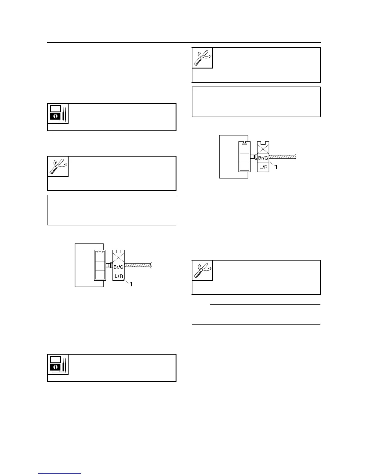
Turn signal/hazard relay output
voltage
DC 12 V
Pocket tester
90890-03112
Analog pocket tester
YU-03112-C
• Positive tester probe →
brown/green “1”
• Negative tester probe →
ground
Pocket tester
90890-03112
Analog pocket tester
YU-03112-C