3.10 Control I/O Connections
u
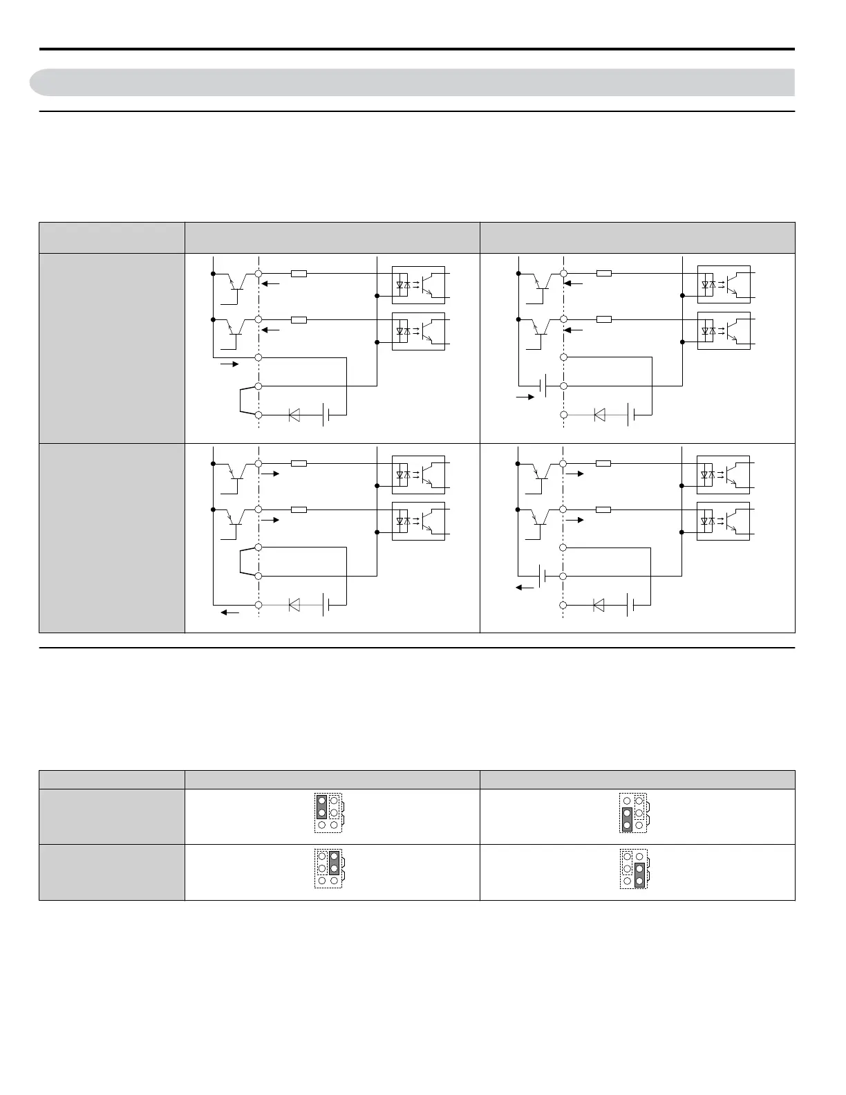
Sinking/Sourcing Mode Switch for Digital Inputs
Use the wire jumper between terminals SC and SP or SC and SN to select between Sink mode, Source mode or external power
supply for the digital inputs S1 to S7 as shown in Table 3.12 (Default: Sink mode, internal power supply).
NOTICE: Do not short terminals SP and SN. Failure to comply will damage the drive.
Table 3.12 Digital Input Sink/Source/External Power Supply Selection
Mode
Drive Internal Power Supply
(Terminals SN and SP)
External 24 Vdc Power Supply
Sinking Mode (NPN)
SC
S7
S6
24 Vdc
SP
SN
External
24 Vdc
Sourcing Mode (PNP)
SC
S7
S6
24 Vdc
SP
SN
External
24 Vdc
u
Input Signal Selection for Terminals A1 and A2
Terminals A1 and A2 can be used to input either a voltage or a current signal. Select the signal type using jumper S1 as
explained in Table 3.13. Set parameters H3-01 and H3-09 accordingly as shown in Table 3.14.
Note: If terminals A1 and A2 are both set for frequency bias (H3-02 = 0 and H3-10 = 0), both input values will be combined to create the frequency
reference.
Table 3.13 Jumper S1 Settings
Terminal Voltage Output Current Output
Terminal A1
Terminal A2
3.10 Control I/O Connections
100
YASKAWA ELECTRIC TOEP C710616 45F YASKAWA AC Drive – Z1000 User Manual

 Loading...


