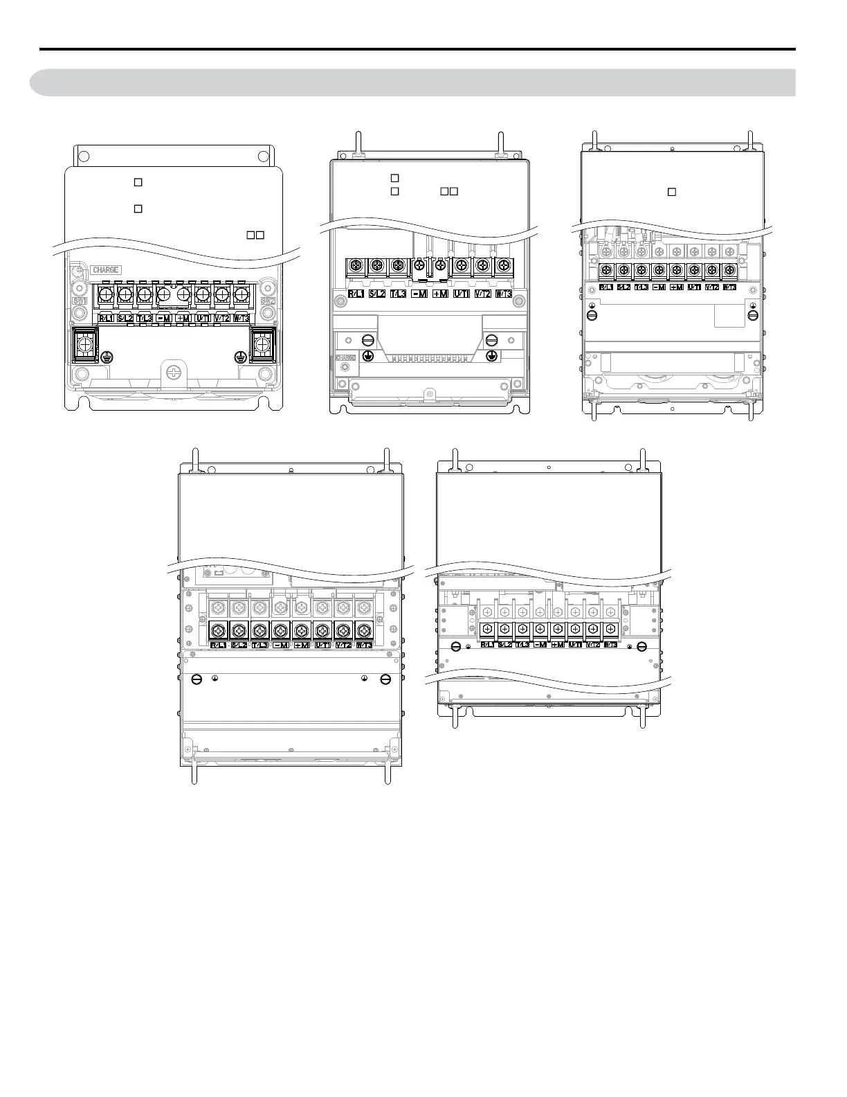
3.4 Terminal Block Configuration
Figure 3.9 and Figure 3.10 show the different main circuit terminal arrangements for the drive capacities.
CIMR-Z 2A0011, 0017, 0024,
0031, 0046, 0059
CIMR-Z 4A0005, 0008, 0011,
0014, 0021, 0027,
0034, 0040,
CIMR-Z 2A0075, 0088, 0114
CIMR-Z 4A0052 A, 0065,
0077, 0096
CIMR-Z 4A0124
CIMR-Z2A0143, 0169, 0211, 0273
CIMR-Z4A0156, 0180, 0240
CIMR-Z4A0302
0052 B
Figure 3.9 Main Circuit Terminal Block Configuration
3.4 Terminal Block Configuration
68
YASKAWA ELECTRIC TOEP C710616 45F YASKAWA AC Drive – Z1000 User Manual

 Loading...


