u
Terminal Configuration
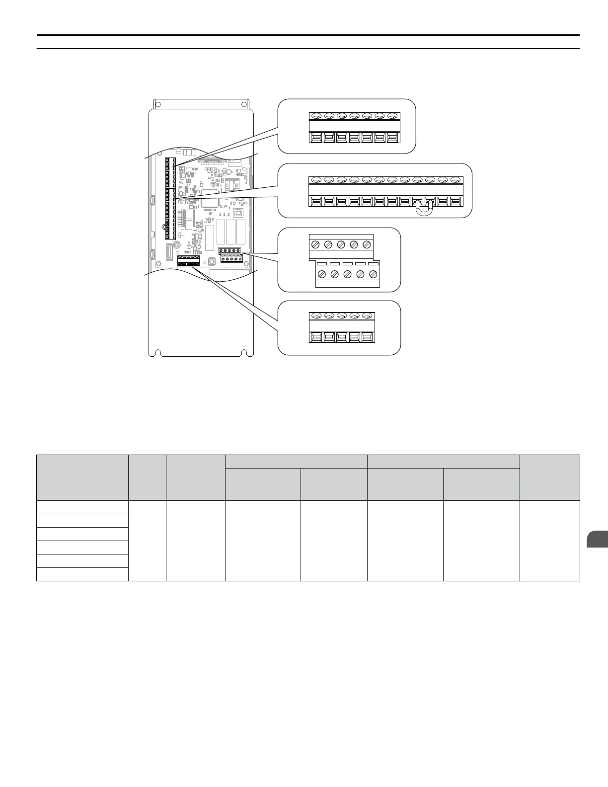
The control circuit terminals are arranged as shown in Figure 3.38.
TB3
TB1
TB2
TB4
+V AC A1 A2 FM AMAC
S1 S2 S3 S4 S5 S6 S7 SN SC SP +P FE
IG R+ R- S+ S-
M3 M4 M5 M6
MA MBMC M1 M2
Figure 3.38 Control Circuit Terminal Arrangement
n
Wire Size and Torque Specifications
Select appropriate wire type and gauges from Table 3.10. For simpler and more reliable wiring, use crimp ferrules on the wire
ends. Refer to Table 3.11 for ferrule terminal types and sizes.
Table 3.10 Wire Gauges
Terminal
Screw
Size
Tightening
Torque
N•m
(lb. in)
Bare Wire Terminal Ferrule-Type Terminal
Wire Type
Applicable
wire size
mm
2
(AWG)
Recomm.
wire size
mm
2
(AWG)
Applicable
wire size
mm
2
(AWG)
Recomm.
wire size
mm
2
(AWG)
S1-S7, SC, SN, SP
M3
0.5 to 0.6
(4.4 to 5.3)
Stranded wire:
0.2 to 1.0
(24 to 17)
Solid wire:
0.2 to 1.5
(24 to 16)
0.75 (18)
0.25 to 0.5
(24 to 20)
0.5 (20)
Shielded wire,
etc.
+V, A1, A2, AC
MA, MB, MC
M1-M6
FM, AM, AC
R+, R-, S+, S-, IG
3.9 Control Circuit Wiring
YASKAWA ELECTRIC TOEP C710616 45F YASKAWA AC Drive – Z1000 User Manual
93
3
Electrical Installation

 Loading...


