No.
(Addr.
Hex)
Name LCD Display Description
Analog
Output Level
Unit
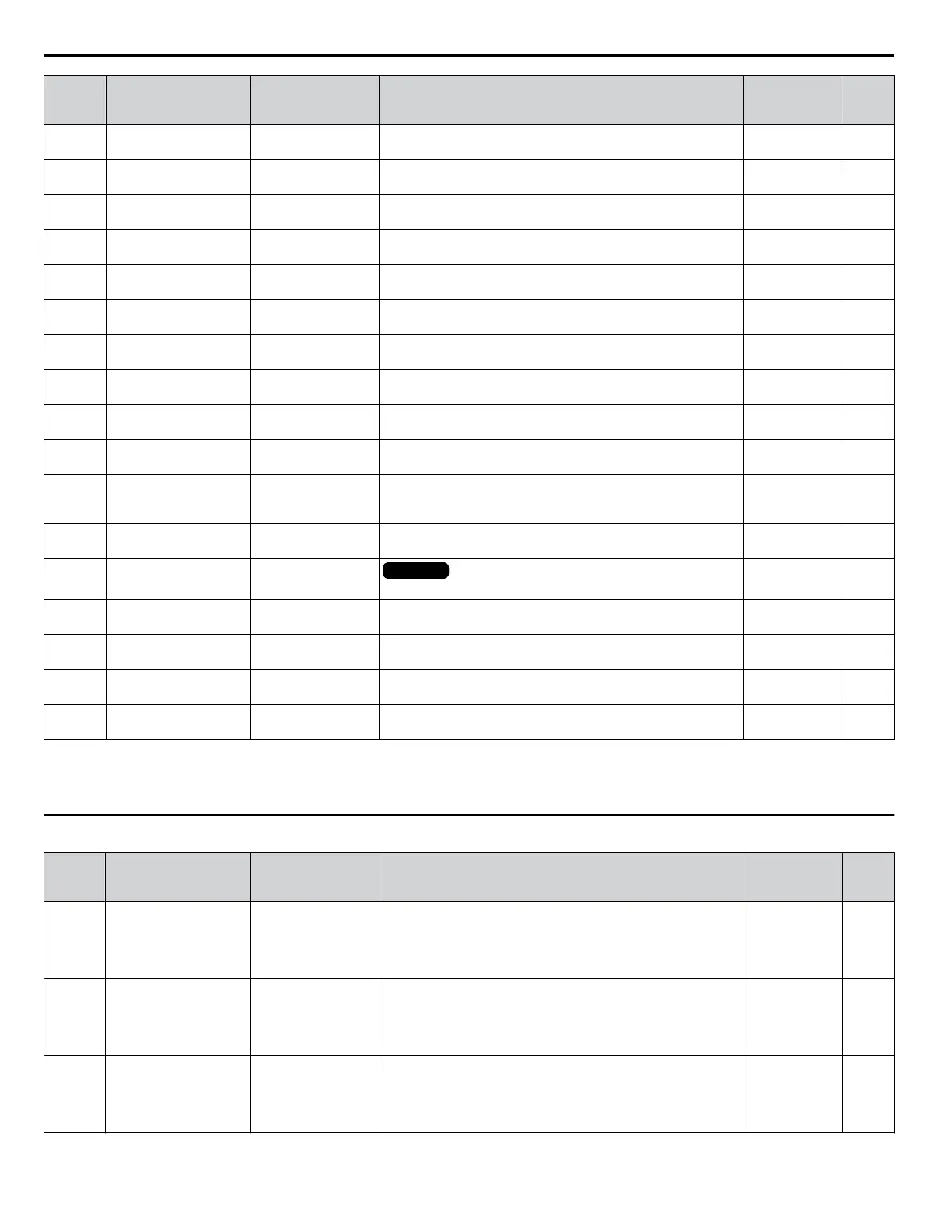
U2-03
(82)
Frequency Reference at
Previous Fault
Frequency Ref
Displays the frequency reference at the previous fault. No signal output
available
0.01 Hz
U2-04
(83)
Output Frequency at
Previous Fault
Output Freq
Displays the output frequency at the previous fault. No signal output
available
0.01 Hz
U2-05
(84)
Output Current at
Previous Fault
Output Current
Displays the output current at the previous fault. No signal output
available
<1>
<2>
U2-07
(86)
Output Voltage at
Previous Fault
Output Voltage
Displays the output voltage at the previous fault. No signal output
available
0.1 Vac
U2-08
(87)
DC Bus Voltage at
Previous Fault
DC Bus Voltage
Displays the DC bus voltage at the previous fault. No signal output
available
1 Vdc
U2-09
(88)
Output Power at
Previous Fault
Output kWatts
Displays the output power at the previous fault. No signal output
available
0.1 kW
U2-11
(8A)
Input Terminal Status at
Previous Fault
Input Term Sts
Displays the input terminal status at the previous fault. Displayed
as in U1-10.
No signal output
available
–
U2-12
(8B)
Output Terminal Status
at Previous Fault
Output Term Sts
Displays the output status at the previous fault. Displays the same
status displayed in U1-11.
No signal output
available
–
U2-13
(8C)
Drive Operation Status
at Previous Fault
Inverter Status
Displays the operation status of the drive at the previous fault.
Displays the same status displayed in U1-12.
No signal output
available
–
U2-14
(8D)
Cumulative Operation
Time at Previous Fault
Elapsed time
Displays the cumulative operation time at the previous fault. No signal output
available
1 h
U2-15
(7E0)
Soft Starter Speed
Reference at Previous
Fault
SFS Output
Displays the speed reference for the soft starter at the previous
fault.
No signal output
available
0.01 Hz
U2-16
(7E1)
Motor q-Axis Current at
Previous Fault
Motor Iq Current
Displays the q-axis current for the motor at the previous fault. No signal output
available
0.10%
U2-17
(7E2)
Motor d-Axis Current at
Previous Fault
Motor Id Current
OLV/PMOLV/PM
Displays the d-axis current for the motor at the previous fault.
No signal output
available
0.10%
U2-20
(8E)
Heatsink Temperature at
Previous Fault
Actual Fin Temp
Displays the temperature of the heatsink when the most recent
fault occurred.
No signal output
available
1 °C
U2-30
(3008)
Date Year at Previous
Fault
Date Year YYYY
Displays the year when the most recent fault occurred. No signal output
available
–
U2-31
(3009)
Date Month and Day at
Previous Fault
Date Mo Day MMDD
Displays the date and day when the most recent fault occurred. No signal output
available
–
U2-32
(300A)
Time Hours and Minutes
at Previous Fault
Time Hr Min HHMM
Displays the time when the most recent fault occurred. No signal output
available
–
<1> This value has two decimal places (0.01 A) if the drive is set for a maximum applicable motor capacity up to and including 11 kW, and one decimal
place (0.1 A) if the maximum applicable motor capacity is higher than 11 kW.
<2> When reading the value of this monitor via MEMOBUS/Modbus, a value of 8192 is equal to 100% of the drive rated output current.
u
U3: Fault History
No.
(Addr.
Hex)
Name LCD Display Description
Analog
Output Level
Unit
U3-01 to
U3-04
(90 to 93
(800 to
803))
First to 4th Most Recent
Fault
Fault Message o
Displays the first to the fourth most recent faults.
No signal output
available
–
U3-05 to
U3-10
(804 to
809)
5th to 10th Most Recent
Fault
Fault Message o
Displays the fifth to the tenth most recent faults.
After ten faults, data for the oldest fault is deleted. The most
recent fault appears in U3-01, with the next most recent fault
appearing in U3-02. The data is moved to the next monitor
parameter each time a fault occurs.
No signal output
available
–
U3-11 to
U3-14
(94 to 97
(80A to
80D))
Cumulative Operation
Time at 1st to 4th Most
Recent Fault
Elapsed Time o
Displays the cumulative operation time when the first to the
fourth most recent faults occurred.
No signal output
available
1 h
B.13 U: Monitors
334
YASKAWA ELECTRIC TOEP C710616 45F YASKAWA AC Drive – Z1000 User Manual

 Loading...


